If you need assistance, please send an email to forum at 4hv dot org. To ensure your email is not marked as spam, please include the phrase "4hv help" in the subject line. You can also find assistance via IRC, at irc.shadowworld.net, room #hvcomm.
Support 4hv.org!
Donate:
4hv.org is hosted on a dedicated server. Unfortunately, this server costs and we rely on the help of site members to keep 4hv.org running. Please consider donating. We will place your name on the thanks list and you'll be helping to keep 4hv.org alive and free for everyone. Members whose names appear in red bold have donated recently. Green bold denotes those who have recently donated to keep the server carbon neutral.
Special Thanks To:
Aaron Holmes
Aaron Wheeler
Adam Horden
Alan Scrimgeour
Andre
Andrew Haynes
Anonymous000
asabase
Austin Weil
barney
Barry
Bert Hickman
Bill Kukowski
Blitzorn
Brandon Paradelas
Bruce Bowling
BubeeMike
Byong Park
Cesiumsponge
Chris F.
Chris Hooper
Corey Worthington
Derek Woodroffe
Dalus
Dan Strother
Daniel Davis
Daniel Uhrenholt
datasheetarchive
Dave Billington
Dave Marshall
David F.
Dennis Rogers
drelectrix
Dr. John Gudenas
Dr. Spark
E.TexasTesla
eastvoltresearch
Eirik Taylor
Erik Dyakov
Erlend^SE
Finn Hammer
Firebug24k
GalliumMan
Gary Peterson
George Slade
GhostNull
Gordon Mcknight
Graham Armitage
Grant
GreySoul
Henry H
IamSmooth
In memory of Leo Powning
Jacob Cash
James Howells
James Pawson
Jeff Greenfield
Jeff Thomas
Jesse Frost
Jim Mitchell
jlr134
Joe Mastroianni
John Forcina
John Oberg
John Willcutt
Jon Newcomb
klugesmith
Leslie Wright
Lutz Hoffman
Mads Barnkob
Martin King
Mats Karlsson
Matt Gibson
Matthew Guidry
mbd
Michael D'Angelo
Mikkel
mileswaldron
mister_rf
Neil Foster
Nick de Smith
Nick Soroka
nicklenorp
Nik
Norman Stanley
Patrick Coleman
Paul Brodie
Paul Jordan
Paul Montgomery
Ped
Peter Krogen
Peter Terren
PhilGood
Richard Feldman
Robert Bush
Royce Bailey
Scott Fusare
Scott Newman
smiffy
Stella
Steven Busic
Steve Conner
Steve Jones
Steve Ward
Sulaiman
Thomas Coyle
Thomas A. Wallace
Thomas W
Timo
Torch
Ulf Jonsson
vasil
Vaxian
vladi mazzilli
wastehl
Weston
William Kim
William N.
William Stehl
Wesley Venis
The aforementioned have contributed financially to the continuing triumph of 4hv.org. They are deserving of my most heartfelt thanks.
Registered Member #2511
Joined: Mon Dec 07 2009, 02:46AM
Location:
Posts: 36
Hello all,
After pondering for about a year I've decided to start constructing an induction heater. The first experiment, using a modified PC powersupply (http://4hv.org/e107_plugins/forum/forum_viewtopic.php?81329) was succesful, even though it was running at very limited power (100W input(measured), estimated 65W RF output).
The goal of the apparatus: about 1kW (but 500W would be satisfactory as well) output at a frequency of about 100 kHz. The topology will most likely be series tank circuit. I will use IRFP460 MOSFETs because that is what I have available (I'm saving the 4*4 pcs. MTE30NE50's on their 4 large cooling fins for a follow-up project, once all the errors are weeded out ). Input power will be 240Vac/50Hz. The intention is to build it right from the first time, as I hate rework/repair.... If needed (due to overheating), I will run it at reduced power - reliability and cool-running are more important than squeezing the last few watts out of it. It's meant to be a useful tool, an addition to my hobby shop, not something that should only 'sorta' work on the electronics bench.
My education and background is as mechanical engineer, not electrical, but know a thing or two about electronics, having tinkered with it from the age of 6. Let's just say I know which end of the soldering iron to hold, but designing high-power switchmode electronics is a tad more challenging than anything I've done so far (for an idea of some of my past projects, feel free to visit here: http://picasaweb.google.com/motorconversion). As this topic is pretty new to me, I'm looking for advice, input, comments, flamings, etc. on what I should do differently.
Above is the design of the inverter part that I have so far; it's only the powersection, the driver section and PLL will follow later. The schematic is a combination of things found in various places, but much of it comes from Richie Burnett (http://www.richieburnett.co.uk/sstate.html
Richie's is the only design I've seen using 1N5822 diodes in series with the FET. So the question is: how necessary are they? I know they work in combination with the MUR1660 (which I intend to replace with the HFA15TB60), but I normally only see freewheel diodes in the bridge schematics. Most likely I will add the 1N5822s (or rather, another set of HFA15TB60's on cooling fins, as I think the 1N5822 are underrated at 3A continuous for a 1kW inverter?)
So the questions:
- Is it ok to replace the 1N5822 with HFA15TB60s? - how necessary are the 1N5822 diodes in practice? - what is your opinion on the snubbers? Needed? Advised? Dimensions (resistance/capacity) seem ok? - what other faults/errors/room for improvement is there in my preliminary schematic? Is there enough capacity (electrolytics)? - how much cooling do you think the freewheel diodes and 'series' diode (1N5822) will need?
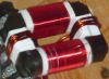
I intend to use the cooling fins below. A large one for each IRFP460 (2 total). By 'feel' I think it's big enough for the purpose, if not, let me know (I don't know how many K/W the fins are, but the large ones are 30x100x80mm). The smaller blank aluminium fins will be used for the HFA15TB60 'series' diodes (i.e. the 1N5822, if the HFA's are a suitable replacement in your opinions). The black fins are meant for the HFA15TB60 freewheel diodes (D-S of the IRFP460's)
I intend to build the inverter on 1.58mm thick copper-clad epoxy board (FR4), with 'traces' milled. This should yield large conducting surfaces (wide traces/fields) with low inductance.
See the image below for the layout so far (note that the freewheeling and 1N5822 diodes still have to be added). The blue lines indicate milled paths. The two large rectangles at the bottom represent the cooling fins for the IRFP460 MOSFETs. The 4 round objects at the top are the electrolytics (4*470uF/200V). The smaller rectangular blocks are film capacitors.
I'm looking for all kinds of feedback that will help to improve the functionality and reliability of the apparatus. It's intended to end up as a stand-alone machine for use in my hobby workshop, meant to be foolproof. There is nothing I dislike more than needing a machine for a job and having to repair it first, so reliability is of prime importance.
Links to the datasheets for the various components I mentioned:
Sorry for the longwinded story, but I hate it when I read stories in forums where people only provide half the information; I think I've given all the relevant information, if not, please ask.
Looking forward to all advice, comments, links etc. that may help in the success of this project.
Registered Member #1232
Joined: Wed Jan 16 2008, 10:53PM
Location: Doon tha Toon!
Posts: 881
The schottky diodes in series with the MOSFETs are to block current flow through the MOSFET's intrinsic body-drain diodes which are very slow. The anti-parallel FRED then provides the new free-wheeling path for the load current when both MOSFETs are off during the deadtime. As for whether they are needed the definitive answer is "It depends!"
In short it depends on how the inverter is tuned relative to the resonant frequency of the tank circuit, and whether this is a parallel resonant or series resonant network.
If you use the LCLR work coil arrangement and control power throughput by detuning the drive frequency on the high side of the tank circuit's own resonant frequency then there is no requirement for blocking the MOSFET's body-drain diodes. The LCLR arrangement presents an inductive load to the inverter when detuned and MOSFETs like a net inductive load best. (You will find most power electronics books assume a net inductive load as inverters typically drive things like motors and transformers where this is a pretty good assumption. That's why the body-diode isolation and bypass often isn't covered.) If you can ensure that it is always tuned such that the load appears at least partly inductive then the load current lags the applied voltage from the inverter and the diodes never see forced reverse recovery. In this case the slow body-drain diodes are adequate.
In instances where the load current is in phase with the applied voltage or leads (net capacitive load) the load current changes direction before the voltage causing the free-wheel diodes to be subject to forced reverse recovery. The MOSFET body-drain diodes are not suitable for operation as FWDs in this mode of operation above a few kHz because of their lousy reverse recovery times. Forced reverse recovery causes huge current spikes at MOSFET turn-on, voltage overshoots, ringing and EMI problems, and often device failures.
In induction heaters I have designed I control the drive frequency to always be above the resonant frequency of the tank circuit, thus ensuring that the current always lags the applied voltage for the LCLR topology. This net inductive load is ideal for MOSFETs used in bridges and half-bridges as it achieves a mode of soft-switching known as ZVS. Zero voltage switching eliminates turn-on switching losses due to device output capacitances and diode reverse-recovery charge.
Again the requirement for snubbers depends entirely on how the converter is operated. If it was me, I would operate in the ZVS mode described above with lagging power factor and if necessary employ lossless snubbing capacitors directly across the MOSFETs. But, to be honest if you haven't got EMI targets to meet, you can probably dispense with the dv/dt limiting and just let the inverter do it's things. Zero voltage switching is a pretty clean way of running the inverter anyway.
If you want to learn more about induction heating power electronics I'd recommend reading the following two papers:
Registered Member #2511
Joined: Mon Dec 07 2009, 02:46AM
Location:
Posts: 36
Thanks for the response Richie.
I was just reading this page of your website (http://www.richieburnett.co.uk/sstate3.html); for some reason I hadn't seen this before, but it seemed to perfectly answer my question....
The PLL circuit I intend to use (based on Hernán Gonzalez's design: (warning, 1.8MB file) also detunes the PLL to higher frequencies (to reduce power, at startup, etc.) However, just to be safe, I think it'd be best to still design/build the inverter in such a way that even if frequency is lower than resonant frequency, the switchers still won't be overloaded - i.e. freewheel diodes and 'series' diodes to isolate the MOSFET intrinsic body diode. It may be redundant, but I like belt-and-braces security, so to speak.
Another question though: on your website, you say: "The body-diode is isolated by means of a Schottky Barrier diode connected in series with the MOSFET drain lead. (Schottky diodes operate due to majority carrier conduction, and therefore do not exhibit any significant reverse recovery time. Essentially, they turn off immediately when the current tries to change direction.)"
My question: *must* the series diode be a Schottky diode? Or can it be a plain (fast-recovery) diode too? This part isn't entirely clear to me yet.
If it must be Schottky, I'll use MBR1545's (have a bunch of them out of PC PSUs; 15A, 45V max, TO220 so can be easily mounted on a cooling fin, though I'm not sure they need the cooling; but I'd rather overbuild than run risks of overloading components)
Interesting remarks on the dead-time too.... I thought more deadtime would be better; or at least that excess deadtime wouldn't do harm. But apparently it can do harm, in that it may overstress the freewheel diodes. Learned something new there. Very thankful for the time and effort you put into your website - it is very much appreciated.
Registered Member #882
Joined: Sat Jul 07 2007, 04:32AM
Location:
Posts: 103
Richie, i've reread your IH section many a time. How have i missed those PDFs? Am i just that blind?
My question: *must* the series diode be a Schottky diode? Or can it be a plain (fast-recovery) diode too? This part isn't entirely clear to me yet
I think what he's saying is that the schottkys are even faster. I suppose the only reason to go with the non-schottky fast recovery diodes would be for higher reverse voltage ratings than schottkys can achieve. Or someother Vdrop or capacitance related design choice.
What i'm not clear on is how schottkys can do the job at all. I just don't understand what voltage they see, is it just the drop across the tank/load+spikes? Otherwise i'd think you'd need a diode there with as high a standoff voltage as your FET.
Registered Member #162
Joined: Mon Feb 13 2006, 10:25AM
Location: United Kingdom
Posts: 3140
Just a minor change to your schematic, mainly to maximise the electrolytics
A) are your electrolytics, since they are rated 400V you can use them in parallel across the DC bus. B) is a resistor to discharge the DC Bus .. could be 22k C) is a low impedance film capacitor to bypass the DC Bus at high frequencies D) are your resonant capacitors.
Your soft-start resistor of 10k seems rather high value, I'd go for 100R wirewound, 10W or more. (wirewound resistors have good at short-term overload capability)
Registered Member #1232
Joined: Wed Jan 16 2008, 10:53PM
Location: Doon tha Toon!
Posts: 881
Schottky diodes are the best choice for blocking the MOSFET's intrinsic body-drain diode for two reasons:
1. They have a low forward-voltage drop, 2. They have a negligible reverse-recovery time
They only need to be rated for about 30V in the reverse blocking direction. This is because when current is in the direction where the Schottky's are reverse biases, the external Fast-recovery free-wheel diode is in conduction. Theoretically the Schottky diodes only need to be able to reverse block up to the forward conduction voltage of the FRED. This means you can use low-voltage Schottky diodes and minimise conduction losses. In practice 30V is a good comprimise for the Schottky diodes since they will see a small voltage spike in addition to the FRED voltage drop as the Free-wheel diodes start to pick up the load current. (The fast recovery free-wheel diodes need to be rated for the full DC bus voltage plus a safety margin however. So until recently these needed to be ultra-fast Silicon Rectifier diodes, however SiC Schottkys with high-voltage ratings are now becoming cheaper.
Registered Member #2511
Joined: Mon Dec 07 2009, 02:46AM
Location:
Posts: 36
Thanks for your comments, Sulaiman and Richie. I have taken note. Have used Schottky diodes (MBRB2545; 25A; 45V) as the series diode (mounted on the same heatsink as the IRFP460; was possible because the cathode of the diodes connects to the tab of the TO220 case, and the drain of the IRFP460 is also connected to the tab of the TO247 case; drain and diode cathode can thus be mounted on the same heatsink, without needing insulation).
The freewheel diodes (HFA15TB60; 15A; 600V; ultrafast, 42ns, TO220 case) have been mounted on their own small heatsink. The end result is that the MOSFET's intrinsic body diodes will be totally isolated.
Sulaiman, have taken note of your modifications too. I admit the softstart resistor seems much too high, will go down to 220 ohm. Will follow your advice on the capacitors too.
BTW, I noticed you eliminated the series capacitor (4*220n); what was your rationale behind this? Don't you think it would be advisory to include it?
Registered Member #882
Joined: Sat Jul 07 2007, 04:32AM
Location:
Posts: 103
This is because when current is in the direction where the Schottky's are reverse biases, the external Fast-recovery free-wheel diode is in conduction.
This site is powered by e107, which is released under the GNU GPL License. All work on this site, except where otherwise noted, is licensed under a Creative Commons Attribution-ShareAlike 2.5 License. By submitting any information to this site, you agree that anything submitted will be so licensed. Please read our Disclaimer and Policies page for information on your rights and responsibilities regarding this site.


 induction heater project - feedback on inverter.

 ). Input power will be 240Vac/50Hz. The intention is to build it right from the first time, as I hate rework/repair.... If needed (due to overheating), I will run it at reduced power - reliability and cool-running are more important than squeezing the last few watts out of it. It's meant to be a useful tool, an addition to my hobby shop, not something that should only 'sorta' work on the electronics bench.