If you need assistance, please send an email to forum at 4hv dot org. To ensure your email is not marked as spam, please include the phrase "4hv help" in the subject line. You can also find assistance via IRC, at irc.shadowworld.net, room #hvcomm.
Support 4hv.org!
Donate:
4hv.org is hosted on a dedicated server. Unfortunately, this server costs and we rely on the help of site members to keep 4hv.org running. Please consider donating. We will place your name on the thanks list and you'll be helping to keep 4hv.org alive and free for everyone. Members whose names appear in red bold have donated recently. Green bold denotes those who have recently donated to keep the server carbon neutral.
Special Thanks To:
Aaron Holmes
Aaron Wheeler
Adam Horden
Alan Scrimgeour
Andre
Andrew Haynes
Anonymous000
asabase
Austin Weil
barney
Barry
Bert Hickman
Bill Kukowski
Blitzorn
Brandon Paradelas
Bruce Bowling
BubeeMike
Byong Park
Cesiumsponge
Chris F.
Chris Hooper
Corey Worthington
Derek Woodroffe
Dalus
Dan Strother
Daniel Davis
Daniel Uhrenholt
datasheetarchive
Dave Billington
Dave Marshall
David F.
Dennis Rogers
drelectrix
Dr. John Gudenas
Dr. Spark
E.TexasTesla
eastvoltresearch
Eirik Taylor
Erik Dyakov
Erlend^SE
Finn Hammer
Firebug24k
GalliumMan
Gary Peterson
George Slade
GhostNull
Gordon Mcknight
Graham Armitage
Grant
GreySoul
Henry H
IamSmooth
In memory of Leo Powning
Jacob Cash
James Howells
James Pawson
Jeff Greenfield
Jeff Thomas
Jesse Frost
Jim Mitchell
jlr134
Joe Mastroianni
John Forcina
John Oberg
John Willcutt
Jon Newcomb
klugesmith
Leslie Wright
Lutz Hoffman
Mads Barnkob
Martin King
Mats Karlsson
Matt Gibson
Matthew Guidry
mbd
Michael D'Angelo
Mikkel
mileswaldron
mister_rf
Neil Foster
Nick de Smith
Nick Soroka
nicklenorp
Nik
Norman Stanley
Patrick Coleman
Paul Brodie
Paul Jordan
Paul Montgomery
Ped
Peter Krogen
Peter Terren
PhilGood
Richard Feldman
Robert Bush
Royce Bailey
Scott Fusare
Scott Newman
smiffy
Stella
Steven Busic
Steve Conner
Steve Jones
Steve Ward
Sulaiman
Thomas Coyle
Thomas A. Wallace
Thomas W
Timo
Torch
Ulf Jonsson
vasil
Vaxian
vladi mazzilli
wastehl
Weston
William Kim
William N.
William Stehl
Wesley Venis
The aforementioned have contributed financially to the continuing triumph of 4hv.org. They are deserving of my most heartfelt thanks.
Registered Member #1497
Joined: Thu May 22 2008, 05:24AM
Location: Toronto, Ontario, Canada
Posts: 801
So I've decided to build a nice big capacitor bank for pulse power experiments, while conventional wisdom says that electrolytic caps aren't up to the job, I'm determined to try otherwise. My plan is to use 38000uF at 450V in electrolytic caps and use a bunch of diodes and SCR's to minimize/eliminate any ringing that would reduce the lifespan or destroy my caps...
I'm going to use a pair of heavy duty (5.3kA peak stud diodes) placed in-line with the load to eliminate most of the ringing, and on top of that I will use 2 puck SCR's (5.5kA peak), one on the +ve side and one on the -ve side of the cap bank, triggered using a GDT so that I get high-side isolation.
I will use another smaller stud SCR to achieve safe-discharge through 3 or 4 incandescent bulbs incase residual charge remained, or due to a failure in the load. Charging will be done either by a cascade with a variac, or by a big boost converter so I can strap a 12V battery to it and use it away from a source of AC. The charging circuit will be connected/disconnected by a DIY contactor I suppose, because the big spike of current and back EMF would likely destroy a small boost converter, and no doubt cause havoc on a 120VAC line.
Also, I have built a rogowski coil and I'll build an active integrator so I can measure the current waveform, and I'll capture it with my laptop soundcard with an attenuator.
The overall design will look like this, minus a few parts:
Construction photos:
Mockup with unflattened copper pipes, one SCR pictured infront, the other in back. Plywood base with caster wheels, eventually there will be a case with handles for easy transportation.
Top-down view of the mockup
Other side
Big diode (in the back) that I'll place across +ve to -ve to get rid of any reverse bias.
Registered Member #1497
Joined: Thu May 22 2008, 05:24AM
Location: Toronto, Ontario, Canada
Posts: 801
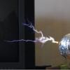
Peak current depends on the inductance of all the connections, and somehow I doubt that the buss-bar layout is optimal, however its still going to be very high, at least 5-10kA. The diodes should ensure that I can safely use inductive loads without back-EMF destroying the caps, which means a coilgun, railgun, can crusher, or even a hdd platter launcher are all possibilities. On the resistive side, I can do wire exploding (or any other mildly conductive object exploding).
Registered Member #1062
Joined: Tue Oct 16 2007, 02:01AM
Location:
Posts: 1529
To make copper flat, just hammer it as flat as you can, turn it around and do that again. I also put a big steel block i found outside on it, and hammer that.
Registered Member #1497
Joined: Thu May 22 2008, 05:24AM
Location: Toronto, Ontario, Canada
Posts: 801
I've only managed to get it reasonably flat, acceptable for a buss bar, but unacceptable for connecting to a hockey puck SCR. I may have to resort to lapping the end of a piece of copper to get it super smooth.
Registered Member #1497
Joined: Thu May 22 2008, 05:24AM
Location: Toronto, Ontario, Canada
Posts: 801
Ok so a few updates:
1. I've cleaned the big stud diode I got for free with some alcohol and it turns out that its a 1n4047, which unfortunately is only rated for 200V. Instead of this big stud diode, I plan to use 1 or 2 isotop packaged dual diodes rated at 500A surge each (at 800V). It may be a bit overkill, but I sampled these and I have no use for them.
2. I've finished flattening the buss bars, probably some time this week I'll make a jig so I can drill the buss bars evenly and bolt the entire thing together.
3. I've figured out how to mount the other SCR puck, so I'll work on that too.
Unfortunately another bout of discussion on my cap bank says that because I am using diodes in series to block any back-EMF, the work-coil may undergo an extreme voltage spike, akin to a buck converter of sorts... I may have to redistribute the diodes so I have one anti-parallel with the load itself, and one in series. The result of a massive voltage spike would be blowing the puck SCR's and charging the bank in reverse, so I may have to use a resistive load with the anti-parallel diode to solve this. I have a big (100W 3ohm) power resistor which may fit the job.
Registered Member #1497
Joined: Thu May 22 2008, 05:24AM
Location: Toronto, Ontario, Canada
Posts: 801
Ok today I made a good amount of progress on the cap bank, drilled the buss bars, positioned and mounted the caps and linked up the 3 sets of caps. The center set of capacitors are shorter than the taller 3100uf ones, so I needed to add a wooden platform to support those caps.
The whole bank currently, note yellow lead, bank was charged up to power and bleed off to test capacitance at low voltage. Yellow lead to short for safety.
A pair of 1awg welding cables, I could use these to join the bank to the test load when I finish it.
This site is powered by e107, which is released under the GNU GPL License. All work on this site, except where otherwise noted, is licensed under a Creative Commons Attribution-ShareAlike 2.5 License. By submitting any information to this site, you agree that anything submitted will be so licensed. Please read our Disclaimer and Policies page for information on your rights and responsibilities regarding this site.


 2.5kJ Capacitor Bank (Complete, finally!)