If you need assistance, please send an email to forum at 4hv dot org. To ensure your email is not marked as spam, please include the phrase "4hv help" in the subject line. You can also find assistance via IRC, at irc.shadowworld.net, room #hvcomm.
Support 4hv.org!
Donate:
4hv.org is hosted on a dedicated server. Unfortunately, this server costs and we rely on the help of site members to keep 4hv.org running. Please consider donating. We will place your name on the thanks list and you'll be helping to keep 4hv.org alive and free for everyone. Members whose names appear in red bold have donated recently. Green bold denotes those who have recently donated to keep the server carbon neutral.
Special Thanks To:
Aaron Holmes
Aaron Wheeler
Adam Horden
Alan Scrimgeour
Andre
Andrew Haynes
Anonymous000
asabase
Austin Weil
barney
Barry
Bert Hickman
Bill Kukowski
Blitzorn
Brandon Paradelas
Bruce Bowling
BubeeMike
Byong Park
Cesiumsponge
Chris F.
Chris Hooper
Corey Worthington
Derek Woodroffe
Dalus
Dan Strother
Daniel Davis
Daniel Uhrenholt
datasheetarchive
Dave Billington
Dave Marshall
David F.
Dennis Rogers
drelectrix
Dr. John Gudenas
Dr. Spark
E.TexasTesla
eastvoltresearch
Eirik Taylor
Erik Dyakov
Erlend^SE
Finn Hammer
Firebug24k
GalliumMan
Gary Peterson
George Slade
GhostNull
Gordon Mcknight
Graham Armitage
Grant
GreySoul
Henry H
IamSmooth
In memory of Leo Powning
Jacob Cash
James Howells
James Pawson
Jeff Greenfield
Jeff Thomas
Jesse Frost
Jim Mitchell
jlr134
Joe Mastroianni
John Forcina
John Oberg
John Willcutt
Jon Newcomb
klugesmith
Leslie Wright
Lutz Hoffman
Mads Barnkob
Martin King
Mats Karlsson
Matt Gibson
Matthew Guidry
mbd
Michael D'Angelo
Mikkel
mileswaldron
mister_rf
Neil Foster
Nick de Smith
Nick Soroka
nicklenorp
Nik
Norman Stanley
Patrick Coleman
Paul Brodie
Paul Jordan
Paul Montgomery
Ped
Peter Krogen
Peter Terren
PhilGood
Richard Feldman
Robert Bush
Royce Bailey
Scott Fusare
Scott Newman
smiffy
Stella
Steven Busic
Steve Conner
Steve Jones
Steve Ward
Sulaiman
Thomas Coyle
Thomas A. Wallace
Thomas W
Timo
Torch
Ulf Jonsson
vasil
Vaxian
vladi mazzilli
wastehl
Weston
William Kim
William N.
William Stehl
Wesley Venis
The aforementioned have contributed financially to the continuing triumph of 4hv.org. They are deserving of my most heartfelt thanks.
Registered Member #95
Joined: Thu Feb 09 2006, 04:57PM
Location: Norway
Posts: 1308
Originally I just bought a bunch of el-cheapo foil caps from ebay on impulse with the intention of trying the LCLR topology again. It worked somewhat with a simple TL494 inverter, but I had to constantly adjust the frequency by hand to keep the capacitor voltage safe or current draw under control. All it would have taken was one slip and the bridge or tank capacitor would die. Meh. And I hadn't even gotten to tuning the matching inductor yet.
So I started designing a driver based on frequency adjustment to regulate the tank voltage, inverter current or inverter/tank phase. Which ever had the highest priority. (The discussion took place silently in this thread.) It would be nothing new actually, as this type of driver has been done before only with discretes. Tim's IH is complicated as hell though, and I wasn't going for something that elaborate. So after many different versions I eventually got something which worked and was reasonably simple. Behold.
As Richie has detailed on his site the LCLR arrangement presents a capacitive load below resonance and inductive above resonance, with inductive reactance being the most forgiving for a square wave inverter. Therefor an increase in supply current or tank voltage brings the VCO frequency up. On either side of resonance the impedance of the LCLR circuit increases, lowering current draw and resonant rise. With low supply voltages or proper loads neither the tank voltage nor the inverter current will need regulation, in which case the driver must lock onto the exact resonant frequency of the LCLR circuit for max efficiency and power. The PLL takes care of this by adjusting the VCO frequency to the point where the inverter output and tank voltage are 90 degrees out of phase (inverter leading the tank voltage), because this phase difference characterizes resonance in a LCLR circuit.
How does it work in the real world? Excellently. With light to no load the voltage or current protection kicks in and keeps the inverter from self destructing. With moderate to heavy loads the PLL kicks in and keeps everything in resonance. I've run it several times over the last few weeks and haven't noticed any odd behaviour yet. The only thing I dislike is that the voltage/current regulation isn't "smooth" but seems to oscillate somewhat. It's hard to explain but you can hear white noise whenever the regulation kicks in. Hasn't caused any noticeable problems though.
Anyway with the new driver finally done I can continue working on the LCLR topology. Atm I've narrowed the limiting factor down to the matching inductor which heats up fast. Before I can do any serious heating I need to make something more robust. Currently the inductor sports 16-filar 0.3mm litz wire, which I thought would be good for 20A at 100kHz. Hence the surprise when it started heating so badly. Is there nothing more to do than wind more litz wire or get copper strips? How does one make a power inductor?
Registered Member #1389
Joined: Thu Mar 13 2008, 12:50AM
Location: Pittsburgh, PA
Posts: 346
I don't know if this is practical, but you could cut some Al flashing into a proper width strip, and turn your matching inductor from that. As I understand it, Aluminum has a larger skin depth than copper, so it may be better in this situation, and the surface area will effectively give you a larger conducting area. Also, the windings may have enough surface area to dissipate generated heat better than the 16 filar litz wire you have.
Registered Member #1232
Joined: Wed Jan 16 2008, 10:53PM
Location: Doon tha Toon!
Posts: 881
Sounds good Uzzors - I'm glad you got the controller working well.
The noise you noticed during current-limiting could be due to instability in the current control loop. Or it might be the sign of a potentially damaging low-frequency resonance between the bridge's DC blocking capacitor and the Lmatch inductor. (The DC blocking cap and Lmatch inductor will series resonate at a lowish frequency. Any control loop oscillation around this frequency is BAD!)
Re: Power inductor design, i'd use a large Mn/Zn ferrite E-core set, gapped and wound with litz. ETD and EC cores are designed to minimise the mean turn length and volume of ferrite, which is fine for a transformer, but it is not really what is wanted here. Power electronics books should cover the magnetics design.
I also doubled up the IRFP450s which reduced power dissipation considerably. With a single fan the inverter can run continuously I believe. Now if only the tank could do the same. The capacitors don't get warm themselves, which isn't bad considering how cheap they were. They do heat up from the immense heat conducted by the work coil though, an insulating crucible would help.
And some mandatory pics of redhot iron. The power of this IH isn't very impressive IMO, but at least it worked as a test bed for my new driver.
Registered Member #1232
Joined: Wed Jan 16 2008, 10:53PM
Location: Doon tha Toon!
Posts: 881
Water cooling of the work coil is essential otherwise it will eventually melt from the hundreds of amps passing through it. As you found it is also subject to the radiant heat of the workpiece too, if there is no thermal "lagging" to insulate the two.
Registered Member #89
Joined: Thu Feb 09 2006, 02:40PM
Location: Zadar, Croatia
Posts: 3145
Hi Uzzors,
Your work is awesome so far, get the water cooling running so you can ramp it up!
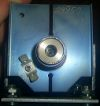
What I'm worried about is very poor heatsinking of your mosfets, and with sil pads, you really need far better if you want to push the little mosfet's limits. Your current heatsink doesn't look like good but for 20..30W of total dissipation.
As you are in any case going to use water cooling, could you make some sort of water blocks for each of those mosfet's - some copper pipe soldered to a copper block would probably be just fine for ~100W of dissipation per mosfet... When properly cooled I think a H bridge of IRFP450's might produce up to 3kVA. Only an estimation with my current experiences though, and not sure how much kW will that actually be in an LCLR IH.
Of course you must not use sil pads, mosfets need to be clamped to blocks directly and insulation provided by long plastic water pipes.
Cooling is one of most important things in power electronics, which many people completely underestimate and then wonder why do their semiconductors die.
Registered Member #941
Joined: Sun Aug 05 2007, 10:09AM
Location: in a swedish junk pile
Posts: 497
is CPU/GPU waterblocks for pc enuf to cool a fet in a config like this ? If yes it would be a great deal since pc water cooling stuff is getting cheap nowdays, and i have some pc wc components, from hdd coolers to cpu/gpu water blocks to pumps and dedicated fluid and radiators.
Registered Member #1374
Joined: Tue Mar 04 2008, 04:14PM
Location: Switzerland
Posts: 10
Hi, I just discovered the website of your project : great, exactly what I need ! I'll try to build someting very similar to yours.
For the matching inductor that heats, have you tried an air-core coil ? 45uH is easily feasible, I think. (I was also never really successful at induction heating, so maybe I'm wrong..)
This site is powered by e107, which is released under the GNU GPL License. All work on this site, except where otherwise noted, is licensed under a Creative Commons Attribution-ShareAlike 2.5 License. By submitting any information to this site, you agree that anything submitted will be so licensed. Please read our Disclaimer and Policies page for information on your rights and responsibilities regarding this site.


 Induction heater (featuring my new PLL driver :-O)