If you need assistance, please send an email to forum at 4hv dot org. To ensure your email is not marked as spam, please include the phrase "4hv help" in the subject line. You can also find assistance via IRC, at irc.shadowworld.net, room #hvcomm.
Support 4hv.org!
Donate:
4hv.org is hosted on a dedicated server. Unfortunately, this server costs and we rely on the help of site members to keep 4hv.org running. Please consider donating. We will place your name on the thanks list and you'll be helping to keep 4hv.org alive and free for everyone. Members whose names appear in red bold have donated recently. Green bold denotes those who have recently donated to keep the server carbon neutral.
Special Thanks To:
Aaron Holmes
Aaron Wheeler
Adam Horden
Alan Scrimgeour
Andre
Andrew Haynes
Anonymous000
asabase
Austin Weil
barney
Barry
Bert Hickman
Bill Kukowski
Blitzorn
Brandon Paradelas
Bruce Bowling
BubeeMike
Byong Park
Cesiumsponge
Chris F.
Chris Hooper
Corey Worthington
Derek Woodroffe
Dalus
Dan Strother
Daniel Davis
Daniel Uhrenholt
datasheetarchive
Dave Billington
Dave Marshall
David F.
Dennis Rogers
drelectrix
Dr. John Gudenas
Dr. Spark
E.TexasTesla
eastvoltresearch
Eirik Taylor
Erik Dyakov
Erlend^SE
Finn Hammer
Firebug24k
GalliumMan
Gary Peterson
George Slade
GhostNull
Gordon Mcknight
Graham Armitage
Grant
GreySoul
Henry H
IamSmooth
In memory of Leo Powning
Jacob Cash
James Howells
James Pawson
Jeff Greenfield
Jeff Thomas
Jesse Frost
Jim Mitchell
jlr134
Joe Mastroianni
John Forcina
John Oberg
John Willcutt
Jon Newcomb
klugesmith
Leslie Wright
Lutz Hoffman
Mads Barnkob
Martin King
Mats Karlsson
Matt Gibson
Matthew Guidry
mbd
Michael D'Angelo
Mikkel
mileswaldron
mister_rf
Neil Foster
Nick de Smith
Nick Soroka
nicklenorp
Nik
Norman Stanley
Patrick Coleman
Paul Brodie
Paul Jordan
Paul Montgomery
Ped
Peter Krogen
Peter Terren
PhilGood
Richard Feldman
Robert Bush
Royce Bailey
Scott Fusare
Scott Newman
smiffy
Stella
Steven Busic
Steve Conner
Steve Jones
Steve Ward
Sulaiman
Thomas Coyle
Thomas A. Wallace
Thomas W
Timo
Torch
Ulf Jonsson
vasil
Vaxian
vladi mazzilli
wastehl
Weston
William Kim
William N.
William Stehl
Wesley Venis
The aforementioned have contributed financially to the continuing triumph of 4hv.org. They are deserving of my most heartfelt thanks.
Registered Member #76
Joined: Thu Feb 09 2006, 10:04AM
Location: Hemer, Germany
Posts: 458
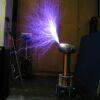
a while ago i thought that i had to start something new. drsstc design is great but after 12 drsstcs i said "hey, what am i doing here.?" so this was the day i started reading. richies site and his 4mhz sstc project made me thoughtfully. but i wanted something new, something cooler. so i started reading about amplitude modulating. well, here it is.
In detail its just a basic Class e amplifier like richie burnett used. i simplified his shematic and played around and this is what i came up with.
the 4 mhz class e part works great and at the moment i still think about the idea to get rid of the big transformer for the audiosignal. unless it sounds really great.
this was the first test of the prototype, so its all really basic. what i want to try is to use a linear regulator like everyone here knows, for powersupplys etc. the linear regulator is set to around 90% of the input voltage. with a smallsignal amplifier the audiosignal is amplified and then fed to the gate of the linear reg causing the output voltage to change. like this.
in theory i should have a output voltage which isrelatively stable over a wide current range with a modulated audiosignal on top of the dc voltage. in my simulations it all works really great and with the amplification factor and output voltage carefully set, the power dissipation should be less than 30Watts for 120Watss output power. my first tests showed me that the class e part works best with an input voltage of around 50 volts,.
im on holiday now, so this project will be updated as soon as i tried this linear reg. for sure, the shematics shown here are just for showing what i mean. the final circuits are much more complex.
Registered Member #56
Joined: Thu Feb 09 2006, 05:02AM
Location: Southern Califorina, USA
Posts: 2445
Sounds like a great project, you should be able to get some really nice sounding audio out of it with such a nice high Fo. It is hard to judge audio quility from a youtube video, but it sounds like you have some kind of nonlinearity in your system (saturating the audio transformer?) that is causing some distorsion.
Registered Member #30
Joined: Fri Feb 03 2006, 10:52AM
Location: Glasgow, Scotland
Posts: 6706
You'll need some kind of RF bypass capacitor between the output of the modulator and the primary coil of the Class-E stage. It's hard to see how it could have worked well without one.
Registered Member #76
Joined: Thu Feb 09 2006, 10:04AM
Location: Hemer, Germany
Posts: 458
mh, maybe i was lucky with the settings. this is my first class e project, so what kind of rf bypass capacitor do you mean? a cap in parallel with the primary, tuned at resonant frequency? ok, the mosfet got warm in my circuit but i ran it for some hours and nothing bad happend. input voltage is around 40-50volts but i tested 100volts as well. sure, the design is not perfect, but for now it works fine. maybe someone who already build class e stages can give me some hints to improve my circuit.
well, there was some disortion due to the audio transformer in my previous circuit. the dc current flowing through the transformer caused the transformer to saturate very quickly, and maybe the bad quality of the selfmade mosfet amp caused more disortion.. thats why i try to get rid of it with this linear reg design. today i want to build it and do some research and tests with different loads to see how rugged it is and how much power dissipation i have to expect.
theres still a lot to do, and thats why i thought to open a project thread to get some suggestions from you
Registered Member #56
Joined: Thu Feb 09 2006, 05:02AM
Location: Southern Califorina, USA
Posts: 2445
I think that he means you need to add a cap from the v+ side of L3 to ground, because as it is the inductance/resistance/losses in general of the audio transformer is being added to L3.
The size for that cap is tricky because having too large of one will kill the high frequency performance.
Also, something that would be interesting to see would be to run this coil strait off of a 'real' audio amplifier. If you coil is drawing 100w at 50v that is 25omhs of impedance--which should be able to work with an audio amplifier without too much trouble. I suppose the biggest problem would be dealing with the nonlinearities of the coil, although it should be possible to inject a DC bais after the dc blocking cap in the amp, although by the time all of that is working it would probably have been easier to just build your own modulator they way you were planning....
Registered Member #89
Joined: Thu Feb 09 2006, 02:40PM
Location: Zadar, Croatia
Posts: 3145
Richie Burnett got around all this a much simpler way as I recall -
He just used two class E amplifiers in push pull, and phase modulated one amplifier with audio.
I don't know how he done that, possibly with some sort of crazy PLL circuit. Power levels and frequencies were of course immense (18Mhz and >1000W with just two IFP460's, I think. Hope I'm not letting out any of his secrets here ).
I don't know much more than that but apparently it is not really worth trying to use some kind of huge amplifier for audio modulation.
I'm not sure how this phase shift modulation sounds, but it may be suffering from supply voltage sag since there's no feedback of any kind to compensate it.
Registered Member #76
Joined: Thu Feb 09 2006, 10:04AM
Location: Hemer, Germany
Posts: 458
well. ive build the linear reg and was surprised. its really difficult to adjust, but it works quite well. its obviously not that powerful than the audio transformer design, mostly due to the induced extra voltage in the transformer design.
40volts is fine, but the modulation ratio is really small and so on the volume is not as good as i expected.
now, that i know, that this design is worth a try, i want to go further. a new linear reg design for voltages up to 100v is the goal.
after that, the prototyping is almost done and i can start working on my stereo design
Registered Member #1232
Joined: Wed Jan 16 2008, 10:53PM
Location: Doon tha Toon!
Posts: 881
If you want to go down the linear high-level AM route I would recommend investigating the Class-H modulator. This arrangement uses a split rail supply and two linear pass elements to give a very respectible efficiency and low distortion for typical audio signals. The modulation efficiency at the quiescent operating point can be nearly 100% because one pass element is in saturation and the other is in cutoff. Excursions of the audio signal either take one device closer to cutoff, or the other device further towards saturation depending on the polarity of the audio waveform. This situation is a significant improvement on a Class A high-level modulator, but without the complexity of a full-blown PWM switching amplifier.
Some info is here:
(It also doesn't require the special modulation transformer to resist saturation due to the DC flowing in the secondary.)
The dog's bollox of high-level AM modulation is the polyphase Class D switching amplifier, but things like this are difficult for a hobbyist to design, build and set up. Or as Marko eluded there are alternative low-level means of introducing modulation such as FM and out-phasing.
This site is powered by e107, which is released under the GNU GPL License. All work on this site, except where otherwise noted, is licensed under a Creative Commons Attribution-ShareAlike 2.5 License. By submitting any information to this site, you agree that anything submitted will be so licensed. Please read our Disclaimer and Policies page for information on your rights and responsibilities regarding this site.


 My 4Mhz amplitude modulated audio sstc


 ).
).