If you need assistance, please send an email to forum at 4hv dot org. To ensure your email is not marked as spam, please include the phrase "4hv help" in the subject line. You can also find assistance via IRC, at irc.shadowworld.net, room #hvcomm.
Support 4hv.org!
Donate:
4hv.org is hosted on a dedicated server. Unfortunately, this server costs and we rely on the help of site members to keep 4hv.org running. Please consider donating. We will place your name on the thanks list and you'll be helping to keep 4hv.org alive and free for everyone. Members whose names appear in red bold have donated recently. Green bold denotes those who have recently donated to keep the server carbon neutral.
Special Thanks To:
Aaron Holmes
Aaron Wheeler
Adam Horden
Alan Scrimgeour
Andre
Andrew Haynes
Anonymous000
asabase
Austin Weil
barney
Barry
Bert Hickman
Bill Kukowski
Blitzorn
Brandon Paradelas
Bruce Bowling
BubeeMike
Byong Park
Cesiumsponge
Chris F.
Chris Hooper
Corey Worthington
Derek Woodroffe
Dalus
Dan Strother
Daniel Davis
Daniel Uhrenholt
datasheetarchive
Dave Billington
Dave Marshall
David F.
Dennis Rogers
drelectrix
Dr. John Gudenas
Dr. Spark
E.TexasTesla
eastvoltresearch
Eirik Taylor
Erik Dyakov
Erlend^SE
Finn Hammer
Firebug24k
GalliumMan
Gary Peterson
George Slade
GhostNull
Gordon Mcknight
Graham Armitage
Grant
GreySoul
Henry H
IamSmooth
In memory of Leo Powning
Jacob Cash
James Howells
James Pawson
Jeff Greenfield
Jeff Thomas
Jesse Frost
Jim Mitchell
jlr134
Joe Mastroianni
John Forcina
John Oberg
John Willcutt
Jon Newcomb
klugesmith
Leslie Wright
Lutz Hoffman
Mads Barnkob
Martin King
Mats Karlsson
Matt Gibson
Matthew Guidry
mbd
Michael D'Angelo
Mikkel
mileswaldron
mister_rf
Neil Foster
Nick de Smith
Nick Soroka
nicklenorp
Nik
Norman Stanley
Patrick Coleman
Paul Brodie
Paul Jordan
Paul Montgomery
Ped
Peter Krogen
Peter Terren
PhilGood
Richard Feldman
Robert Bush
Royce Bailey
Scott Fusare
Scott Newman
smiffy
Stella
Steven Busic
Steve Conner
Steve Jones
Steve Ward
Sulaiman
Thomas Coyle
Thomas A. Wallace
Thomas W
Timo
Torch
Ulf Jonsson
vasil
Vaxian
vladi mazzilli
wastehl
Weston
William Kim
William N.
William Stehl
Wesley Venis
The aforementioned have contributed financially to the continuing triumph of 4hv.org. They are deserving of my most heartfelt thanks.
Registered Member #10
Joined: Thu Feb 02 2006, 09:45AM
Location: Bunbury, Australia
Posts: 1424
This is an odd little high voltage generator which is in principle, part Blumlein generator (like the nitrogen laser uses) and part induction coil. It is very simple and compact and very easy to make. They have two copper strips insulated from each other and rolled up like a rolled capacitor. Apply a few kV at one end of both strips and they will charge up. Short circuit one end with a spark gap and a very fast pulse passes in the Blumlein capacitor strips. This will have a magnetic effect as the current in each copper strip (my brain starts to hurt here) will have an additive effect and like current in a coil will result in magnetic induction in the remaining turns of copper strip.
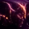
The first photo shows the spiral impulse generator generating a 5 mm spark (perhaps 5 kV) from a 1 mm spark gap. The spark gap is between the two electrodes (which are not connected to each other) and the right upper electrode is the one that continues through to the output electrode strip with the longer spark coming off it. The capacitance between the two strips is 900 pF.
The second photo shows the 1984 patent that this comes from. The next photo shows the strips of copper foil of 10 x 62 mm. I have soldered two together for the long winding. Hence there are two parallel strips of 4.5 turns and one strip only continues on for another 4.5 turns. The last photo shows the start of the copper strip windings separated by polyethylene sheet. It doesn't seem too efficient but I don't really understand the setup enough to know which way to modify it best. I imagine that I could make one with more turns to start.
Registered Member #543
Joined: Tue Feb 20 2007, 04:26PM
Location: UK
Posts: 4992
How intriguing!
I have found another patent, which discusses the problems of increasing the power output of the basic spiral, in order to put forward a method of its own for reaching into the megavolt range from a 10kV supply:
Multi winding spiral generator United States Patent 5567995
Registered Member #95
Joined: Thu Feb 09 2006, 04:57PM
Location: Norway
Posts: 1308
It seems like these can have large multiplication ratios. The one here has a step up ratio of 16 at 9kV! A simple alternative to Marx generators maybe, if we can figure out how to make them that efficient.
Registered Member #75
Joined: Thu Feb 09 2006, 09:30AM
Location: Montana, USA
Posts: 711
Wow, what an amazing concept. I went right ahead and tried to make one
but I could not get it to work yet. Maybe it is a little small, is is constructed from a single rolled up overhead sheet so the "secondary" (is it still called that in electrodynamics?) is only 70cm long or so, which is about a third of what Peter has. I'll keep playing with it though, especially the thread linked to by Uzzors makes it seem really worthwhile. I'll have to be able to puncture that OHP sheet!
EDIT: Well, I sort of got it to work by cutting down on the extra insulation material (pun intended). Still the output spark is rather puny, about the same as a piezo lighter.
I don't think there is anything magical or electrodynamical about this circuit as I build it, at least I can explain without the electric field vectors, traveling waves, reflections and all that. After all it IS just a Tesla coil with tank capacitor and the primary scrambled up. So it does not take the slightest bit of waves propagating at the speed of light to get a spark at the output. I am pretty sure the "real" Blümlein pulseforming lines, which are used for creating nanosecond pulses, take a lot more work that just rolling up a piece of tinfoil. Have a look here for some Blümlein bashing, although that may just be a minority opinion.
Registered Member #543
Joined: Tue Feb 20 2007, 04:26PM
Location: UK
Posts: 4992
Dr. Shark wrote ...
I am pretty sure the "real" Blümlein pulseforming lines, which are used for creating nanosecond pulses, take a lot more work that just rolling up a piece of tinfoil. Have a look here for some Blümlein bashing, although that may just be a minority opinion.
N2 lasers need nanosecond pumping, which makes a practical Blumlein difficult to implement, but more usual Blumlein configurations in the microsecond pulse range are not at all difficult to construct, and drive with a rotary spark gap, as this paper shows:
You just need to have the money to buy RG213 coaxial cable!
Registered Member #1321
Joined: Sat Feb 16 2008, 03:22AM
Location:
Posts: 843
Somewhere I have a few pdf papers on these things. If anyone is interested maybe I can try to find them and upload them somewhere.
The one paper I don't have is the one referenced in the following linked paper, which apparently discusses the detailed design.
(Wrt blumlein pulse generators it seems that the limiting factor for short, fast pulses is the switch...for fast di/dt you need high electric field across the spark gap which generally means pressurized gas or a liquid dielectric. BTW here's an interesting paper on a fast blumlein pulser
Registered Member #10
Joined: Thu Feb 02 2006, 09:45AM
Location: Bunbury, Australia
Posts: 1424
Here are a couple of diagrams to clarify the setup. There is no connection between the two HV electrodes. It does not resemble a TC at all (although something similar might be feasible but that is another project). There is a standard two parallel electrode strips rolled up like a home made rolled cap. The extended one just allows more voltage step up. Actually, I don't know how much induction there really is and how much is just transmission line coupling.
BTW for all those who wondered why their rolled caps failed at the ends, this is why. A few weeks ago, I autopsied 2 of my old big rolled caps to dispose of the oil and the failure was at the ends away from the electrode attachment, ie where the HV is picked up.
Registered Member #1025
Joined: Sun Sept 23 2007, 07:53PM
Location: Czech Rep.
Posts: 566
I have few ideas regarding this thread...
What about to try coax cable istead of the rolled-insutated stripes...Would it work?
And it would be interesting to try solidstate based "spark gap" because as understand this concept it has no real frequency limit (maybe such device could be used for plasma speakers ???)
This site is powered by e107, which is released under the GNU GPL License. All work on this site, except where otherwise noted, is licensed under a Creative Commons Attribution-ShareAlike 2.5 License. By submitting any information to this site, you agree that anything submitted will be so licensed. Please read our Disclaimer and Policies page for information on your rights and responsibilities regarding this site.


 Spiral impulse generator = rolled cap Blumlein induction coil!