If you need assistance, please send an email to forum at 4hv dot org. To ensure your email is not marked as spam, please include the phrase "4hv help" in the subject line. You can also find assistance via IRC, at irc.shadowworld.net, room #hvcomm.
Support 4hv.org!
Donate:
4hv.org is hosted on a dedicated server. Unfortunately, this server costs and we rely on the help of site members to keep 4hv.org running. Please consider donating. We will place your name on the thanks list and you'll be helping to keep 4hv.org alive and free for everyone. Members whose names appear in red bold have donated recently. Green bold denotes those who have recently donated to keep the server carbon neutral.
Special Thanks To:
Aaron Holmes
Aaron Wheeler
Adam Horden
Alan Scrimgeour
Andre
Andrew Haynes
Anonymous000
asabase
Austin Weil
barney
Barry
Bert Hickman
Bill Kukowski
Blitzorn
Brandon Paradelas
Bruce Bowling
BubeeMike
Byong Park
Cesiumsponge
Chris F.
Chris Hooper
Corey Worthington
Derek Woodroffe
Dalus
Dan Strother
Daniel Davis
Daniel Uhrenholt
datasheetarchive
Dave Billington
Dave Marshall
David F.
Dennis Rogers
drelectrix
Dr. John Gudenas
Dr. Spark
E.TexasTesla
eastvoltresearch
Eirik Taylor
Erik Dyakov
Erlend^SE
Finn Hammer
Firebug24k
GalliumMan
Gary Peterson
George Slade
GhostNull
Gordon Mcknight
Graham Armitage
Grant
GreySoul
Henry H
IamSmooth
In memory of Leo Powning
Jacob Cash
James Howells
James Pawson
Jeff Greenfield
Jeff Thomas
Jesse Frost
Jim Mitchell
jlr134
Joe Mastroianni
John Forcina
John Oberg
John Willcutt
Jon Newcomb
klugesmith
Leslie Wright
Lutz Hoffman
Mads Barnkob
Martin King
Mats Karlsson
Matt Gibson
Matthew Guidry
mbd
Michael D'Angelo
Mikkel
mileswaldron
mister_rf
Neil Foster
Nick de Smith
Nick Soroka
nicklenorp
Nik
Norman Stanley
Patrick Coleman
Paul Brodie
Paul Jordan
Paul Montgomery
Ped
Peter Krogen
Peter Terren
PhilGood
Richard Feldman
Robert Bush
Royce Bailey
Scott Fusare
Scott Newman
smiffy
Stella
Steven Busic
Steve Conner
Steve Jones
Steve Ward
Sulaiman
Thomas Coyle
Thomas A. Wallace
Thomas W
Timo
Torch
Ulf Jonsson
vasil
Vaxian
vladi mazzilli
wastehl
Weston
William Kim
William N.
William Stehl
Wesley Venis
The aforementioned have contributed financially to the continuing triumph of 4hv.org. They are deserving of my most heartfelt thanks.
Registered Member #1025
Joined: Sun Sept 23 2007, 07:53PM
Location: Czech Rep.
Posts: 566
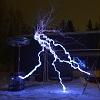
I‘m starting a new HV project... For my future experiments I need 300KV DC power source and here is the try to get it for low costs… It is classical CW multiplier, based on ignition coil 50KV at 6 KHz. In fact it is just next step after the doubler which I presented here recently. The caps are home made disassembled from my old Marx generator which I’m actually trying to replace.
The diodes are stacks of 1N4007 , probably the cheapest diodes you can get (I bought 1000pc for 20$) dipped in cooking oil. So theoretically I can rectify 1milion volts…
Here is a test run - two stages. Spark gap is 15cm, probably I can go much widther. The sparking rate is approx. 15 per second and sound is really loud . I plan at least 8 stages in the future so hopefully I’ll send more exiting picture soon…
I’ll have to think a lot how to design the 8 stages into a compact device (probaly everythnig will end up inside an oil bath). Any suggestion regarding this would be great. And of course any question and comments are welcomed…
Registered Member #964
Joined: Wed Aug 22 2007, 12:39AM
Location: Stockton, CA
Posts: 134
Wow, that's amazing. Though I can;t see that lighter sitting in spark gap going to well lol. 300kv is alot, don't you get enough corona to fill a bunch of 2 liter bottles? Either way, congrats. so far the only hv thingy I've gotten to work is a kit that makes like 1/2-1" sparks... lol.
How much time did you spend trying to make this thing work? So far I can;t even make a camera-flash inverter based CW multiplier work.. Anyway, hope you eventualy manage the big 1mill! Be sure to post pictures when you do! lol
Registered Member #1025
Joined: Sun Sept 23 2007, 07:53PM
Location: Czech Rep.
Posts: 566
Spedy wrote ...
300kv is alot, don't you get enough corona to fill a bunch of 2 liter bottles?
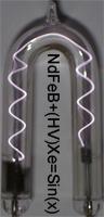
You do not understand it well, 300KV is the aim which is still far away. My guess is, that with those 2 stages my final tension is little bit above 100KV. Corona does not seem to be a problem. You can check the darker picture...
Spedy wrote ...
How much time did you spend trying to make this thing work?
This project is glued of parts of my older ones. Thus, completing this thing was a quick action. Only soldering the diodes is PITA work. Today I've made another stage with new caps which are 30% less capacitance. I plan to reduce the capacitance gradually with each next stage. I placed everything on a plastic board so it is much more compact now. With the test run I scared to death a friend of mine I'll send new pictures tomorrow
Registered Member #690
Joined: Tue May 08 2007, 03:47AM
Location: New Jersey, USA
Posts: 616
You should really use a limiting resistor, since every time you directly short that you discharge the capacitor string through the 1A rated 1N4007s. Seems you've had no problems so far, but once you get up to higher stored energy it could be bad news for those diodes.
Registered Member #1025
Joined: Sun Sept 23 2007, 07:53PM
Location: Czech Rep.
Posts: 566
Shaun wrote ...
You should really use a limiting resistor, since every time you directly short that you discharge the capacitor string through the 1A rated 1N4007s. Seems you've had no problems so far, but once you get up to higher stored energy it could be bad news for those diodes.
That's actually very good point Shaun. This is exactly the reason why I'm discussing the whole project here. Any design flaws you people notice are thankfully accepted. I didn't realize that this is not a Marx and amp peak must be really big in the diodes during discharge (It must be a good luck and gods support they are still alive ). I will use 1Mohm resistor made of 10pc of 100K/2W high voltage resistors all dipped in oil. I've been using them for my Marx and I know for sure that 3 of them in series can stand 60KV. I'm very curios how the sparks will look like with this type of limiter... Thanks...
Registered Member #964
Joined: Wed Aug 22 2007, 12:39AM
Location: Stockton, CA
Posts: 134
Ah, I see. a 300kv goal is pretty high by my standards lol.
I can understand how those diode chains can be a pain, I've burned myself numerous times trying to make a little tiny CW where all the components hardly have any leads at all >.<
Hey, what circuit are you using for the iggy coil? 50kv ac from an iggy seems kinda insane to me...
Registered Member #1025
Joined: Sun Sept 23 2007, 07:53PM
Location: Czech Rep.
Posts: 566
Here is my latest progress. I made the whole device more compact and added one more stage. I also built the HV resistor as you can see on the picture.
However, despite I’m still far away from my aim I already have to deal with serious problems. The resistors works only if the spark gap is below 22cm. If I make larger gap the initial few sparks are not resistor limited (the electricity finds somehow way around). I also noticed that I have flashovers between the connection points within the device in case the spark gap is more than 26cm. This means I’ll have to built the final device differently with greater spacing or/and placing it inside an oil bath . I’m sending at least some sparks pictures limited by the resistor. The HV terminals are 22cm apart…
This site is powered by e107, which is released under the GNU GPL License. All work on this site, except where otherwise noted, is licensed under a Creative Commons Attribution-ShareAlike 2.5 License. By submitting any information to this site, you agree that anything submitted will be so licensed. Please read our Disclaimer and Policies page for information on your rights and responsibilities regarding this site.


 300KV Cockroft Walton multiplier


 . I plan at least 8 stages in the future so hopefully I’ll send more exiting picture soon…


 I'll send new pictures tomorrow
 ). I will use 1Mohm resistor made of 10pc of 100K/2W high voltage resistors all dipped in oil. I've been using them for my Marx and I know for sure that 3 of them in series can stand 60KV. I'm very curios how the sparks will look like with this type of limiter...
 . I’m sending at least some sparks pictures limited by the resistor. The HV terminals are 22cm apart…