If you need assistance, please send an email to forum at 4hv dot org. To ensure your email is not marked as spam, please include the phrase "4hv help" in the subject line. You can also find assistance via IRC, at irc.shadowworld.net, room #hvcomm.
Support 4hv.org!
Donate:
4hv.org is hosted on a dedicated server. Unfortunately, this server costs and we rely on the help of site members to keep 4hv.org running. Please consider donating. We will place your name on the thanks list and you'll be helping to keep 4hv.org alive and free for everyone. Members whose names appear in red bold have donated recently. Green bold denotes those who have recently donated to keep the server carbon neutral.
Special Thanks To:
Aaron Holmes
Aaron Wheeler
Adam Horden
Alan Scrimgeour
Andre
Andrew Haynes
Anonymous000
asabase
Austin Weil
barney
Barry
Bert Hickman
Bill Kukowski
Blitzorn
Brandon Paradelas
Bruce Bowling
BubeeMike
Byong Park
Cesiumsponge
Chris F.
Chris Hooper
Corey Worthington
Derek Woodroffe
Dalus
Dan Strother
Daniel Davis
Daniel Uhrenholt
datasheetarchive
Dave Billington
Dave Marshall
David F.
Dennis Rogers
drelectrix
Dr. John Gudenas
Dr. Spark
E.TexasTesla
eastvoltresearch
Eirik Taylor
Erik Dyakov
Erlend^SE
Finn Hammer
Firebug24k
GalliumMan
Gary Peterson
George Slade
GhostNull
Gordon Mcknight
Graham Armitage
Grant
GreySoul
Henry H
IamSmooth
In memory of Leo Powning
Jacob Cash
James Howells
James Pawson
Jeff Greenfield
Jeff Thomas
Jesse Frost
Jim Mitchell
jlr134
Joe Mastroianni
John Forcina
John Oberg
John Willcutt
Jon Newcomb
klugesmith
Leslie Wright
Lutz Hoffman
Mads Barnkob
Martin King
Mats Karlsson
Matt Gibson
Matthew Guidry
mbd
Michael D'Angelo
Mikkel
mileswaldron
mister_rf
Neil Foster
Nick de Smith
Nick Soroka
nicklenorp
Nik
Norman Stanley
Patrick Coleman
Paul Brodie
Paul Jordan
Paul Montgomery
Ped
Peter Krogen
Peter Terren
PhilGood
Richard Feldman
Robert Bush
Royce Bailey
Scott Fusare
Scott Newman
smiffy
Stella
Steven Busic
Steve Conner
Steve Jones
Steve Ward
Sulaiman
Thomas Coyle
Thomas A. Wallace
Thomas W
Timo
Torch
Ulf Jonsson
vasil
Vaxian
vladi mazzilli
wastehl
Weston
William Kim
William N.
William Stehl
Wesley Venis
The aforementioned have contributed financially to the continuing triumph of 4hv.org. They are deserving of my most heartfelt thanks.
Registered Member #30656
Joined: Tue Jul 30 2013, 02:40AM
Location: UK
Posts: 208
In contrast to my normal method (build something without notes or photographs, get confused later), I've decided to have a go at documenting my QCW project as I build it. Hopefully this will both help others with their builds, and me when I come back and try and figure out what the heck I did!
Basic primary/secondary specs: - Secondary 110mm dia, 285mm wound length, ~800 turns (guess!) of 0.315mm wire - 300x75mm spun toroid - Primary of 9.5mm dia tube, 10 turns, "solenoid" wound on 160mm dia. former. With strike rail, but may remove this later. - Coupling of ~0.4-0.5 (some adjustment possible) - 24.8nF primary cap (gives relatively low tank impedance, hopefully works out OK!)
With the above setup (shown below with original ducting toroid, subsequently upgraded to spun), we get the following: - Primary and secondary resonance both ~260-280kHz - Upper pole of coupled coils lies at ~360kHz (see graph for measurement of primary impedance with secondary present). If this is not high enough once the coil is loaded by streamers, I will need to change the primary/MMC or secondary (or both) to raise the frequency.
Drive details: - Initially planning to use phase-shift modulation, will switch to buck modulator if unsuccessful or if I need to push more power than hard-switching will allow. - MMC split into 8 sections, 4 in parallel on each side of primary coil (see MSPAINT drawing, but ignore the incorrect MMC spec and CT location) - Each MMC section driven by an independent half bridge. This guarantees reasonable sharing of current and switching losses between parallel bridges. - 8 half bridge modules on individual PCBs, each with 2x FGH40N60SMD IGBT. May upgrade to FGH60N60SMD (mainly for significantly lower junction-case thermal impedance). - Each IGBT on an individual heatsink to eliminate insulation pads and their relatively large thermal impedance. Main reason for this is to lower the transient thermal impedance of the system, and thus the delta-temperature seen by the IGBT die during each pulse.
MMC details: - 24.8nF formed of 8 sections of 12.4nF (2s4p). Each section on individual PCB. - Each section uses 32x 6.2nF/1600V B32672 TDK EPCOS capacitors in 8p4s configuration for 12.4nF/6.4kV - 12.8kV DC rating (AC peak rating at low duty cycle is similar - caps are specified for greater than nominal voltage operation) for full MMC - Current rated at >30A RMS, >600Apk @ ~350kHz - 256 capacitors total, with 512 bleed resistors (_NOT_ looking forward to soldering this). Caps were cheap though, <40 GBP total.
Gate drive and control: - Will use a gate drive PCB located under the half bridge modules - This PCB takes logic-level gate drive signals (will upgrade to RS485 for noise immunity) over shielded ethernet cables, and drives 2x gate drive transformers located on the PCB. - These transformers have a low inductance connection to the half-bridge PCBs via ribbon cable - Also takes in outputs from 50:1 commercial CTs located on half of the bridge PCBs (CT outputs connected in parallel to add current together). These are run into a second set of 3 CTs (in series) to give an overall 1000:1 reduction with 3 isolated outputs (for OCD, feedback and monitoring). This is experimental, and may be too high a step-down ratio for a QCW design with it's relatively low current, but is the best I can do with commercial CTs. By using 4 separate CTs and keeping them on the bridge outputs rather than one CT on a primary coil connection we avoid the need to insulate the CT from high voltage (present on both ends of the primary in this design). - For driving 8 half-bridges, requires a second "slave" PCB with 2 more GDTs on it. This is simply a sub-equiped version of the first PCB, with connection between the two via ribbon cable. - Gate drive control via a separate PCB, un-designed at this point, but will likely use a combination of a microcontroller and CPLD/FPGA, or a PSoc. - Driver feature wish-list (i.e. will likely never get around to a lot of these!): * Phase shift or buck modulator support * Freewheeling (pulse-skipping) support * Softstart/phase controlled rectifier support * PFC voltage/current setpoint control (if I ever build a PFC) * Control via optical/bluetooth serial link/protocol, rather than the simple interrupter type control * Readback of values to handheld controller, e.g. peak current, bus voltage etc * Some sort of MIDI/music support to piss people off with Nyan Cat midis
PCBs: To do all of the stuff above I intend to build most of the electronics on properly made PCBs. I've documented and release the first 3 that I've designed in the following github repositories: . - Each has a readme file that should be looked at, and schematics/renders in the "Reference Outputs" folder - I have concerns over the clearance distances, especially on the GDT PCB. I take no reponsibility if anyone copies what I've done and doesn't treat everything (even low voltage stuff) as live! - The GDT PCB in particular needs a new revision to be made. - All 3 are being fabbed right now, so are completely untested as of now! - Also see thread here: for an earlier revision of the IGBT bridge PCB (probably more generally useful, as allows for more heatsink options).
Registered Member #61302
Joined: Mon Nov 21 2016, 03:09AM
Location:
Posts: 4
Seems like Phil didn't read the description.
I just built a dual-bridge coil, using many of the same techniques (MMC paralleling, individual, un-isolated heatsinks, PCB MMC), so this is very familiar.
I also used the same CT scheme you're describing. However, for my first CT stages, I wound my own, in order to get a low ratio. I think the little bit of extra work was worth the overall simplification in wiring. Instead of mounting them on the board, I stuck 'em on aluminum standoffs. This gave me the overall ratio I desired (400:1) and the low turns ratio on the first stage gave plenty of volt-time headroom on the second stage.
Registered Member #30656
Joined: Tue Jul 30 2013, 02:40AM
Location: UK
Posts: 208
Phillip Slawinski wrote ...
Looks like a fun project.
Question: why did you locate the feedback CT on the HV side? Why not pass the four LV leads to one side of the MMC through the CT?
As Chris mentioned, I actually did locate it on the LV side; the diagram is wrong as noted in my explanation text - I'm putting one (inexpensive commercial high frequency rated) 1:50 CT on each PCB that forms one side of the bridge (4 total), their outputs are combined in parallel to be fed into the second stage CT.
This was done as it gave me a nice convenient part i could solder to the board without winding, eliminated needing to thread wires through and terminate the output (I intend to pass the bridge output to the MMC with M4 brass standoffs, so keeping it on-PCB helps here), and I had some spare pins on my ribbon cable to use for the output.
The whole scheme with the 1:50 cascaded with the 3x 1:20 CTs gives 1:1000, which is a little bit more than I'd like, but i decided to give it a go as it keeps everything nice and tidy. If needed I'll increase the burden resistors a bit to push up the feedback voltage a bit. Note that I have the ability to look at the gain/phase of the CTs up to 10MHz, so I'll know if it's doing worse than the proven DIY method (which I've verified is _very_ good, with low phase shift and flat gain well past DRSSTC frequencies).
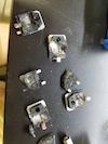
I've attached a picture of the 1:50 CT mounted to a board with heatsinks etc (note that the standoffs are not the final ones I'll use), and will add more later once I've done more of the soldering. Am still waiting on the 1:20CTs so won't be able to test that part of the design till at least next week.
Chris - good to hear that others have gone this route of multi-bridge, split MMC, individual heatsinks etc! Is it working well? What kind of performance are you managing from the coil? I have more devices but less substantial heatsinks than you, so hopefully it works well.
I see that you've used a lot of ceramic caps on your bus - is there a particular part that you found worked well? I've found that it's not so easy to pick them - many parts either have horrible decrease in capacitance (loss of 80% or more) with voltage, or don't specify it at all.
Registered Member #61302
Joined: Mon Nov 21 2016, 03:09AM
Location:
Posts: 4
The pic I sent is an old one; I've moved to film from ceramic, but the boards are essentially the same. I became aware of the problems with voltage effects, and I had some failures that were probably caused by stress cracking of the caps.
Performance of the coil has been generally decent. It behaves essentially like a lower-power version of Phil's "skinny coil". I wanted good thermal performance, but without water cooling.
I've also been toying with the idea of restoring a short-lived coil of mine with the same bridge design, but can never seem to get around to it.
This site is powered by e107, which is released under the GNU GPL License. All work on this site, except where otherwise noted, is licensed under a Creative Commons Attribution-ShareAlike 2.5 License. By submitting any information to this site, you agree that anything submitted will be so licensed. Please read our Disclaimer and Policies page for information on your rights and responsibilities regarding this site.


 QCW build thread (inc. PCB documentation)