If you need assistance, please send an email to forum at 4hv dot org. To ensure your email is not marked as spam, please include the phrase "4hv help" in the subject line. You can also find assistance via IRC, at irc.shadowworld.net, room #hvcomm.
Support 4hv.org!
Donate:
4hv.org is hosted on a dedicated server. Unfortunately, this server costs and we rely on the help of site members to keep 4hv.org running. Please consider donating. We will place your name on the thanks list and you'll be helping to keep 4hv.org alive and free for everyone. Members whose names appear in red bold have donated recently. Green bold denotes those who have recently donated to keep the server carbon neutral.
Special Thanks To:
Aaron Holmes
Aaron Wheeler
Adam Horden
Alan Scrimgeour
Andre
Andrew Haynes
Anonymous000
asabase
Austin Weil
barney
Barry
Bert Hickman
Bill Kukowski
Blitzorn
Brandon Paradelas
Bruce Bowling
BubeeMike
Byong Park
Cesiumsponge
Chris F.
Chris Hooper
Corey Worthington
Derek Woodroffe
Dalus
Dan Strother
Daniel Davis
Daniel Uhrenholt
datasheetarchive
Dave Billington
Dave Marshall
David F.
Dennis Rogers
drelectrix
Dr. John Gudenas
Dr. Spark
E.TexasTesla
eastvoltresearch
Eirik Taylor
Erik Dyakov
Erlend^SE
Finn Hammer
Firebug24k
GalliumMan
Gary Peterson
George Slade
GhostNull
Gordon Mcknight
Graham Armitage
Grant
GreySoul
Henry H
IamSmooth
In memory of Leo Powning
Jacob Cash
James Howells
James Pawson
Jeff Greenfield
Jeff Thomas
Jesse Frost
Jim Mitchell
jlr134
Joe Mastroianni
John Forcina
John Oberg
John Willcutt
Jon Newcomb
klugesmith
Leslie Wright
Lutz Hoffman
Mads Barnkob
Martin King
Mats Karlsson
Matt Gibson
Matthew Guidry
mbd
Michael D'Angelo
Mikkel
mileswaldron
mister_rf
Neil Foster
Nick de Smith
Nick Soroka
nicklenorp
Nik
Norman Stanley
Patrick Coleman
Paul Brodie
Paul Jordan
Paul Montgomery
Ped
Peter Krogen
Peter Terren
PhilGood
Richard Feldman
Robert Bush
Royce Bailey
Scott Fusare
Scott Newman
smiffy
Stella
Steven Busic
Steve Conner
Steve Jones
Steve Ward
Sulaiman
Thomas Coyle
Thomas A. Wallace
Thomas W
Timo
Torch
Ulf Jonsson
vasil
Vaxian
vladi mazzilli
wastehl
Weston
William Kim
William N.
William Stehl
Wesley Venis
The aforementioned have contributed financially to the continuing triumph of 4hv.org. They are deserving of my most heartfelt thanks.
Registered Member #205
Joined: Sat Feb 18 2006, 11:59AM
Location: Skørping, Denmark
Posts: 741
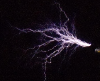
A QCW coil is a demanding task, because there are more than usual disciplines involved. The prospecting builder has to be able to write code, in order to generate the ramp signal that serves as the reference voltage in the Buck converter. He has to be able to transmit this signal in PWM form across a fiber optic link. He has to be able to build same Buck converter. He has to be able to build the coil itself, and understand fine points in tuning it, so that it behaves as wished, and shoots out enormous streamers that don't branch out.
For me, the lack of coding skills has kept me off a project like this for years, but just recently, it came to me, that coding is perhaps not necessarily so hard to do, so as my second coding exercise, I took on writing the code for a ramp signal, and this first post is about this code.
My platform is the Arduino Due, which has a 32 bit ARM processor, and has facilities to easily adjust PWM frequency. These were the reasons I bought it, and the fact that it can be had for 20 bucks is a good enough reason to stick with it. This is how it looks at the moment:
Since Gao Guangyan has the most comprehensive description of the QCW, (And a warm THANK YOU! for that) it came natural to me to write code that could do the same things as his ramp generator, so what you get is 1, An adjustable pulse length, 2, Adjustable amplitude, 3, Simultaneusly adjustable pulse length and amplitude, so that ramp rate is preserved, 4, Adjustable BPS 5, Adjustable level of start up "Wick" level 6, As an extra bonus, I also added the feature of "skewing" the ramp to give exponential or logarithmic shape.
You can see the functions live in this little video:
I have successfully transmittted the signal across 20 meters of 1mm fiber, using the Avago SFH756V emitter as well as the Industrial Fiberoptics IF-D96 and as receiver I use Avago SFH551V. These are middle of the road speed units, however it is possible to transmit 10 bit granularity at 75kHz, which is not so sloppy at all. I use 8 bit and 40 kHz since it gives me a cleaner scope trace to look at.
In the spirit of sharing, and with a wish to get a broader understanding of building and tuning QCW coils, I hereby offer the Ramp generator Code to the community:
Edit:
But, But, But, I have to make it functional, together with a "run" button, and a "single shot" button, so I took the code off again, until I have this figured out.
Registered Member #205
Joined: Sat Feb 18 2006, 11:59AM
Location: Skørping, Denmark
Posts: 741
All,
A little update on the weekend progress. The Buck Converter will consist of a bank of dual 6000uF 450V electrolytics (And a Warm thank you to Sulaiman for saving these for me) for a total of 12000uF.
Next in line is a Powerex CM400DY-12NF (Bought a couple of them cheap ages ago, thinking they'd be good for a DRSSTC, -untill I realized they are 600V types ) which will act as high side switch. Low side switch will remain closed, but it's freewheling diode will act as the return diode, when the main switch is closed.
The output inductor is made from 44 turns of 64 strand 0.34mm, on an old welding transformer core. This wire is a leftover from my dated CCPS transformer and has been sitting on a shelf for 8 years, so good to see it finally come to use.
Using just one core, the Inductance is 70 uH, using both cores, the target inductance of 100uH is acheived with a gap of 12mm, and with 5mm of gap, the inductance is 220uH, so there is a nice range to experiment with. Opening the core up will create eddy currents in the windings that cut the fringe magnetic field from the gap, but given the low duty cycle of this converter, it probably doesn't matter.
The output capacitor is an array of 8 pcs. 2.5uF 600VDC 942C capacitors for a total of 20uF. I had them left over from the prototype of the Danfoss coil, a OLTC I built back in 2004.
Yes, I really scrounged the shelves for parts this time. -Oh, almost forgot, I can even reuse one of the gate driver modules I made for Thumper back in 2010 The whole thing is wrapped up in Phenolic base, alluminum sides and FR4 topplate. The UD2.7C board you see is just a placeholder for the final BuckController board, not yet conceived.
It is satisfying to build these kinds of things.
I'l have to look into putting a start switch into the code, one that doesn't interfere with the main loop, interrupts?, I guess so.
Registered Member #2750
Joined: Sun Mar 21 2010, 08:47PM
Location: Poland
Posts: 46
Hi Finn
Nice to see that you started to work on QCW. I am really impressed with all your tesla coil projects. All of my coils work on your Predikter and I think it is the best driver of all time - I never had any trouble with it - no spikes, no ringing, no fails ;) I have just started to observe this topic and I look forward to further progress. I count on it that's what's created here will be the most impressive QCW ever made :)
Registered Member #205
Joined: Sat Feb 18 2006, 11:59AM
Location: Skørping, Denmark
Posts: 741
Dzejwor, Justin.
Thanks for your kind words, and Dzejwor, before you get your hopes up too high, don't forget who we are playing with.....
Anyway, the last week has mainly been used trying to iron out the code for the buck, and finally with help over at the Arduino forum, the last timing issues were solved just this morning. Today I started the buck up in slave driven mode, just free wheeling with a function generator as metronome. It behaves as it should, putting out half of the Buss voltage at 50% duty cycle, and it is in this mode that the parameters for the snubber can be determined nice and easy.
There is a recommended procedure, requiring to put a capacitor from switch node to ground, which will double the ringing frequency, and then series that capacitor with a suitable resistor, to get the best compromise between ringing amplitude, duration and heat dissipation.
I found that 20nF and a nice 2.2 ohm power resistor in a TO220 package worked exceedingly well, reducing ringing from 100% overshoot to 25%, I think I will stick with that. The 20nF is a bit more than recommended, but I don't mind burning up a bit more power in this low duty cycle converter in exchange of keeping the ringing nice and tight.
The load I use is a 200W 4.7ohm baby I made a couple of winters ago, when I worked on a A Buck Current-fed Push-Pull Converter A project that I never quite finished, due to the complication of a feedback compensation network, which I just could not wrap my head around.
This time, the buck is going to be a free running dragster, with just a simple comparator with a bit of hysteresis to set frequency, and that is hopefully a lot easier. I hope to get the first results tomorrow. It should be quite fun to watch it rip up along that saw tooth reference voltage.
Oh! I'm on the market for some nice mica capacitors, preferably Sangamo or Cornell Dubilier 292, 293, or 294 types. Why don't you drop by over at sale and trade to review an interesting offer i have.....
Registered Member #205
Joined: Sat Feb 18 2006, 11:59AM
Location: Skørping, Denmark
Posts: 741
All,
I thought it might be usefull to inform about methods to reduce noise on the switch node. Yesterday I determined the parameters of a good snubber, but there is another method, and it is to slow down the switching speed of the transistor, with a gate resistor. I added from 2.2 to 10 ohms of resistance in the gate drive, and 10 ohms was the value that gave the best effect.
The resulting waveform can be seen here, with 100V on the bus, 47 Vout into 4.7 ohms, 10A, no overshoot and no ringing. This should provide for a quiet environment in the bottom deck of the QCW.
There is 500nS delay in the optocoupler, which is a TLP250, this will get better when I replace it with a FOD3184. This delay can be seen between Cyan trace, which is gate signal into the driver board, and yellow, which is the gate signal. Then there is another 1uS, untill the IGBT switches, as seen on Magenta Trace. Blue is Inductor Delta current, in this case -+ 3 Amps
The snubber and gate resistors are mounted on the heatsink, because they both get hot.
Off to design the Comparator circuit for the Buck.
Registered Member #205
Joined: Sat Feb 18 2006, 11:59AM
Location: Skørping, Denmark
Posts: 741
All,
Certainly not the sweet and smooth waveform that we have gotten used to looking at, over at Loneoceans, but then, this is just me, and it is still very early in the process. Learning as I go, more and more of the converter gets fixed into it's final shape, and soon all the circuit will be assembled on a single board, not the breadboard mess it is right now.
r
But hey! It works!.
I did not have any really fast comparators on hand, -or rather-, the AD790'es that I planned to use were all broken, so I used an AD311, not a big deal, I'l get some better ones in the mail soon, what matters is that it worked and actually tracked the reference ramp. The switching frequency is 5kHz, and that needs to get a lot higher to get a smooth voltage curve, so that is where I will focus my attention.
Registered Member #1403
Joined: Tue Mar 18 2008, 06:05PM
Location: Denmark, Odense C
Posts: 1968
Hi Finn
I am almost overjoyed to see you undertake a new project again, because you take your time to bring us on the journey, it is wonderful to read about your progress through failures and experiments, that usually end up in world class products :)
About the gate resistors vs snubbers, you understood it correctly, a important dicipline in power electronics is to switch fast as slow as possible :)
Some day you guys have matured the QCW enough for me to venture into it, my own experiments with a ghetto coil are still a massive pile of failures so far!
Registered Member #205
Joined: Sat Feb 18 2006, 11:59AM
Location: Skørping, Denmark
Posts: 741
All,
Mads, thank you for your kind words. The failures, oh yes. Boy do I feel rusty these days, and I am not going to let you down when it comes to failures, like when the hot end of the feedback voltage divider shorted, and took the resistors out all over the breadboard. Nothing fried except the resistors, though.
Anyway, the buck works, but only up to 12kHz. If I turn the hysteresis down any lower, I get bad glitches and the output can look bad, like this:
This is with 340 Volts on the bus, and and 200Volts peak into 2 Ohms, so 100A. Not so shabby for a breadboard design
But it often looks like this:
Every project comes to a point where it has to be cast in copper, and here is the mk.1 of a series of prototype buck converter driver boards: (oh yes: I forgot to turn up the clearance on the supply pads tsk tsk )
Hopefully, this board will enable higher frequency and fewer glitches.
Registered Member #2750
Joined: Sun Mar 21 2010, 08:47PM
Location: Poland
Posts: 46
Everything looks very good now and seems to be better than mine two attempts to QCW buck converter. I tried with simple comparator design like Loneoceans. I get similar glitches at around 30kHz but I didnt' try to lowering switching ferquency. I tried to use TL494 as driver too and generaly it worked nice at around 70kHz but unstable at low load - my output inductor and capacitor tends to fall in resonance. As long as the energy drawn from the system was greater than necessary to excite the resonant circuit, nothing happened. But when it fall under the magic value I get current ringup like drsstc primary and I finaly blew up my buck IGBT this way with realy LOUD bang so it looks like that you have failures is included in the unit cost of this fun. There is no need to break down just keep trying.
This site is powered by e107, which is released under the GNU GPL License. All work on this site, except where otherwise noted, is licensed under a Creative Commons Attribution-ShareAlike 2.5 License. By submitting any information to this site, you agree that anything submitted will be so licensed. Please read our Disclaimer and Policies page for information on your rights and responsibilities regarding this site.


 The road to a QCW


 ) which will act as high side switch. Low side switch will remain closed, but it's freewheling diode will act as the return diode, when the main switch is closed.


 and I finaly blew up my buck IGBT this way with realy LOUD bang
  so it looks like that you have failures is included in the unit cost of this fun. There is no need to break down just keep trying.