If you need assistance, please send an email to forum at 4hv dot org. To ensure your email is not marked as spam, please include the phrase "4hv help" in the subject line. You can also find assistance via IRC, at irc.shadowworld.net, room #hvcomm.
Support 4hv.org!
Donate:
4hv.org is hosted on a dedicated server. Unfortunately, this server costs and we rely on the help of site members to keep 4hv.org running. Please consider donating. We will place your name on the thanks list and you'll be helping to keep 4hv.org alive and free for everyone. Members whose names appear in red bold have donated recently. Green bold denotes those who have recently donated to keep the server carbon neutral.
Special Thanks To:
Aaron Holmes
Aaron Wheeler
Adam Horden
Alan Scrimgeour
Andre
Andrew Haynes
Anonymous000
asabase
Austin Weil
barney
Barry
Bert Hickman
Bill Kukowski
Blitzorn
Brandon Paradelas
Bruce Bowling
BubeeMike
Byong Park
Cesiumsponge
Chris F.
Chris Hooper
Corey Worthington
Derek Woodroffe
Dalus
Dan Strother
Daniel Davis
Daniel Uhrenholt
datasheetarchive
Dave Billington
Dave Marshall
David F.
Dennis Rogers
drelectrix
Dr. John Gudenas
Dr. Spark
E.TexasTesla
eastvoltresearch
Eirik Taylor
Erik Dyakov
Erlend^SE
Finn Hammer
Firebug24k
GalliumMan
Gary Peterson
George Slade
GhostNull
Gordon Mcknight
Graham Armitage
Grant
GreySoul
Henry H
IamSmooth
In memory of Leo Powning
Jacob Cash
James Howells
James Pawson
Jeff Greenfield
Jeff Thomas
Jesse Frost
Jim Mitchell
jlr134
Joe Mastroianni
John Forcina
John Oberg
John Willcutt
Jon Newcomb
klugesmith
Leslie Wright
Lutz Hoffman
Mads Barnkob
Martin King
Mats Karlsson
Matt Gibson
Matthew Guidry
mbd
Michael D'Angelo
Mikkel
mileswaldron
mister_rf
Neil Foster
Nick de Smith
Nick Soroka
nicklenorp
Nik
Norman Stanley
Patrick Coleman
Paul Brodie
Paul Jordan
Paul Montgomery
Ped
Peter Krogen
Peter Terren
PhilGood
Richard Feldman
Robert Bush
Royce Bailey
Scott Fusare
Scott Newman
smiffy
Stella
Steven Busic
Steve Conner
Steve Jones
Steve Ward
Sulaiman
Thomas Coyle
Thomas A. Wallace
Thomas W
Timo
Torch
Ulf Jonsson
vasil
Vaxian
vladi mazzilli
wastehl
Weston
William Kim
William N.
William Stehl
Wesley Venis
The aforementioned have contributed financially to the continuing triumph of 4hv.org. They are deserving of my most heartfelt thanks.
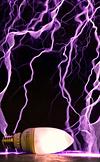
I recently got some white Semikron IGBTs which seem to be more common in Europe than in the US, (vs the black Powerex / Mitsubishi IGBTs). So I thought it would be a good exercise to build a medium sized coil from these IGBTs, and I thought I'll start a thread to document the design and construction progress. These IGBTs are the ultra-fast variety (125 series 400A) which seem to be designed for high frequency resonant inverter operation. I have only used CMx00 IGBTs, so I'll find out how well these stack up against the competition, seeing that there aren't too many Semikron IGBT coils around the forum. Steve Conner's Odin coil comes to mind.
The first thing I did was to work around my constraints, and started designing the bridge in CAD as a very rough layout. I had a bunch of nice Itelcond capacitors on hand so these will form the main bus capacitors, which will be mounted on a laminated bus directly to the IGBTs for the lowest possible bus inductance. The frame will be made of basic 80-20 aluminium framing.
In deciding the operating frequency of the coil, I wanted to balance the frequency with being low enough for the IGBTs to handle, but not too low for it to become annoying to wind (too thin wire). I decided on a 8" secondary to reduce the number of turns, and the length to be about 30" - though the size was basically the largest pipe I could fit on a lathe I happen to have access to. Adding a suitably sized toroid about the same size of the coil, this gave me an operating frequency for about 60 - 65kHz with AWG 26 wire. I haven't decided how I would get the toroid done, but this could be a spun toroid, or a fancy spiral toroid inspired by zrg's large coil.
For the tank capacitors, I decided to use large snubber capacitors - again parts I had on hand, which will give me a good 375nF capacitor bank at lots of volts and lots of Irms capability. From this, I did a quick mockup of how the coil will look like and it should stand about 5 feet tall.
Since the coil looks about right, it's time for construction! Stay tuned as the project progresses.
Registered Member #1403
Joined: Tue Mar 18 2008, 06:05PM
Location: Denmark, Odense C
Posts: 1968
Looks good and you seem to have all the basic numbers in the proper ratios. A medium coil like this should pose no particular problem.
A few things you should consider
- The aluminium frame might be too close to the primary and could present a closed 1 turn loop that would eat power.
- Watch the voltage rating of the power resistors on the heat sink. If you are burning off two too different potentials, you might risk flash over to the heat sink .
Thanks these were indeed things I were considering during the design. I decided on 80/20 because they're easy to put together and the workshop I have access to has a lot of leftover small parts. Because of the same issue you talked about, you can see that I raised the primary up on stands away from that top square 'ring'. I believe it will eat power, but hopefully not too much. Depending on how this works, I'll also try to see if a gap is required or not.
For the resistor question, I was also concerned about this and checked the datasheet to make sure. It seems like the rated operating voltage is (P*R)^0.5, which puts me just around 1.2kV for the bleeder resistor. The 25W packages are rated for 1kVrms and the 50W packages 2kVrms, so I think they should hold up.
Right now I've got most of the parts of the bridge so I'll begin constructing that soon!
Question for people who have used Semikron bricks before - what sort of current do you push these guys to? Mine are 400A IGBTs so I think 800A would be good for robustness, and 1.2kA should still be ok, despite the Icrm being only 600A :)
Registered Member #30656
Joined: Tue Jul 30 2013, 02:40AM
Location: UK
Posts: 208
I've pushed the 200A 125s to at least 650A at ~80kHz without issue. Nice and quick, much less ringing than with CM300s. 400A at 300kHz (!) worked too for a short run :).
Saturation voltage is pretty high, otherwise they seem great. I ended up putting CM300s into my coil instead, but that was mainly because they were more proven performers for ~1kA peak current.
Edit: actually it was 750A, as in this post: Seems they've been pushed much harder too, that thread is probably quite useful for you.
Registered Member #135
Joined: Sat Feb 11 2006, 12:06AM
Location: Anywhere is fine
Posts: 1735
Hey I got a question here, When you guys build these things on a metal base, which acts like a shorted secondary turn, how do you deal with the current flowing through the metal?
At high power does the base even get warm? and how much actual power loss is there would you estimate?
I've pushed the 200A 125s to at least 650A at ~80kHz without issue. Nice and quick, much less ringing than with CM300s. 400A at 300kHz (!) worked too for a short run :).
Saturation voltage is pretty high, otherwise they seem great. I ended up putting CM300s into my coil instead, but that was mainly because they were more proven performers for ~1kA peak current.
Edit: actually it was 750A, as in this post: Seems they've been pushed much harder too, that thread is probably quite useful for you.
Hydron thanks that was very useful! It's good to hear that the 200A 125s have had good performance from some coils! so I think I can safely push these IGBTs to 1.2kA I think! That's correct as well, it looks like conductive losses will be higher due to the higher saturation voltage, but they do seem to have less switching loss than the CM300s. It also seems like Steve Conner's Odin coil didn't have good luck with the T4 IGBTs, but his new bridge of 400A 123s look to be doing well making 9 feet of spark at around 1+kA, as with Eric reporting 1.2kA with 200A 125s. So with this coil, hopefully I'll be able to add another data point :) for these IGBTs.
Hazmatt_(The Underdog) wrote ...
Hey I got a question here, When you guys build these things on a metal base, which acts like a shorted secondary turn, how do you deal with the current flowing through the metal?
At high power does the base even get warm? and how much actual power loss is there would you estimate?
What do you mean metal base? I found that any metal plate near or middle of the primary coil gets blisteringly hot in a short amount of time (tens of seconds), since my first DRSSTC had a metal plate at the bottom of the secondary acting as the ground connector, and I quickly found out how hot it got! However, it didn't seem to cause much % power loss since when I removed it I didn't see any noticeable change in performance.
More progress has been made. Here are continued updates.
I finalized the bridge design and it uses an integrated rectifier, laminated bus and voltage doubler. This allows me to put all connections on the bus plates and it turned out better than I thought it would in the computer! So it's time to build it.
I drilled and tapped the mounting holes on a large heatsink. This went easily enough since I had everything in CAD and I could just print out a to-scale drawing and punch out the holes :). The mounting brackets and bleeder resistors were also mounted, along with the two Semikron bricks.
The laminated bus was cut out from aluminium and fiberglass sheeting and glued together. The result is a little bit rough on the edges since it's hand made, but I think it turned out pretty good.
In goes the bus caps. It's nice how everything finally came together exactly as it looked like in CAD.
The MMC is pretty large, but at 150Arms it should be more than enough for the coil. I made some nice acrylic supports for it.
Overall I think I'm quite happy with how this came out.
Thanks for the comments everyone! Would also appreciate any suggestions or ideas as I go along.
Continuing on the project, the bridge and MMCs were getting hard to move around since they're quite heavy, so I got started working on the enclosure. I got some aluminium framing measured and sawed up, and started putting them together.
Framing is relatively easy to put together, if not somewhat expensive. However this got together quite fast with a cordless screwdriver.
I also bought some nice caster wheels for the coil since I expect this to be quite heavy when it's done.
Finally I cut up a piece of polycarbonate which will act as the main base for the coil. The nice thing about using this framing is that I plan to simply cut out side-panels which will slot directly into the grooves of the frame. I tried to make the sides to be the golden ratio; no idea if this makes it look nicer or not
Next up will be to make the primary coil platform and supports, and to wind the primary coil. The secondary coil needs to be done early as well since it'll take some time for the varnish to dry once it is wound.
This site is powered by e107, which is released under the GNU GPL License. All work on this site, except where otherwise noted, is licensed under a Creative Commons Attribution-ShareAlike 2.5 License. By submitting any information to this site, you agree that anything submitted will be so licensed. Please read our Disclaimer and Policies page for information on your rights and responsibilities regarding this site.


 Semikron DRSSTC Twin Coils!