If you need assistance, please send an email to forum at 4hv dot org. To ensure your email is not marked as spam, please include the phrase "4hv help" in the subject line. You can also find assistance via IRC, at irc.shadowworld.net, room #hvcomm.
Support 4hv.org!
Donate:
4hv.org is hosted on a dedicated server. Unfortunately, this server costs and we rely on the help of site members to keep 4hv.org running. Please consider donating. We will place your name on the thanks list and you'll be helping to keep 4hv.org alive and free for everyone. Members whose names appear in red bold have donated recently. Green bold denotes those who have recently donated to keep the server carbon neutral.
Special Thanks To:
Aaron Holmes
Aaron Wheeler
Adam Horden
Alan Scrimgeour
Andre
Andrew Haynes
Anonymous000
asabase
Austin Weil
barney
Barry
Bert Hickman
Bill Kukowski
Blitzorn
Brandon Paradelas
Bruce Bowling
BubeeMike
Byong Park
Cesiumsponge
Chris F.
Chris Hooper
Corey Worthington
Derek Woodroffe
Dalus
Dan Strother
Daniel Davis
Daniel Uhrenholt
datasheetarchive
Dave Billington
Dave Marshall
David F.
Dennis Rogers
drelectrix
Dr. John Gudenas
Dr. Spark
E.TexasTesla
eastvoltresearch
Eirik Taylor
Erik Dyakov
Erlend^SE
Finn Hammer
Firebug24k
GalliumMan
Gary Peterson
George Slade
GhostNull
Gordon Mcknight
Graham Armitage
Grant
GreySoul
Henry H
IamSmooth
In memory of Leo Powning
Jacob Cash
James Howells
James Pawson
Jeff Greenfield
Jeff Thomas
Jesse Frost
Jim Mitchell
jlr134
Joe Mastroianni
John Forcina
John Oberg
John Willcutt
Jon Newcomb
klugesmith
Leslie Wright
Lutz Hoffman
Mads Barnkob
Martin King
Mats Karlsson
Matt Gibson
Matthew Guidry
mbd
Michael D'Angelo
Mikkel
mileswaldron
mister_rf
Neil Foster
Nick de Smith
Nick Soroka
nicklenorp
Nik
Norman Stanley
Patrick Coleman
Paul Brodie
Paul Jordan
Paul Montgomery
Ped
Peter Krogen
Peter Terren
PhilGood
Richard Feldman
Robert Bush
Royce Bailey
Scott Fusare
Scott Newman
smiffy
Stella
Steven Busic
Steve Conner
Steve Jones
Steve Ward
Sulaiman
Thomas Coyle
Thomas A. Wallace
Thomas W
Timo
Torch
Ulf Jonsson
vasil
Vaxian
vladi mazzilli
wastehl
Weston
William Kim
William N.
William Stehl
Wesley Venis
The aforementioned have contributed financially to the continuing triumph of 4hv.org. They are deserving of my most heartfelt thanks.
Registered Member #4074
Joined: Mon Aug 29 2011, 06:58AM
Location: Australia
Posts: 335
Hey everyone.
I'm currently designing and building a small SSTC (slowly due to work and other stuff). I think I have a good idea of what end goals I want to achieve.
I currently have the components for these things, or assembly has already started: - A typical half bridge inverter with FGH40N60SMD IGBTs and Epcos N30 GDT - Secondary coil is 50mm x approx 290mm, wound with either 32 or 34 AWG (was a long time ago). It's aluminium toroid is around 150mm in diameter and 38mm thick. Resonant freq is roughly 465 kHz. - Standard-issue "diode trick" 555 interrupter for variable ON and OFF times - DC supplies, 12V 2A linear regulator and rectified 230V for the main bus - Epcos N30 Feedback CT
Now I just need to decide on a feedback method that will suit my goals. I was originally looking at the 4046 IC's until I was told that they are nightmarishly fiddly (thanks for the warning, Sigurthr), so now I'm leaning back towards the good old Schmitt trigger design with a 74HC14 IC. However, I'm worried I'll run into stability issues, especially if I draw an arc from the toroid with a grounded electrode.
Here's an idea of the capabilities I want from this coil: - Durability and reliability above all, especially with regard to continuous ground arcs and large changes in frequency due to objects being placed on or near the toroid. - Ability to survive CW runs at 325 VDC for up to 5 minutes, with the interrupter allowing longer run times at a reduced duty cycle (I'll probably just need to adjust the number of turns on the primary coil until I get to the desired power level) - Ability to switch between filtered and unfiltered DC supplies, for both silent CW operation as well as creating a 50 or 100 Hz tone (this should be the easiest to implement, perhaps a couple of relays to switch between full wave and half wave rectification, as well as connecting the smoothing caps)
Would it be possible to get away with the simple 74HC14 design, or will I run the risk of detonating my bridge while drawing arcs with a grounded object? Unless I'm missing something vital, it seems the Schmitt trigger design is capable of momentarily switching the bridge at a higher harmonic, generating huge switching losses? Or is it actually much more stable in practice?
Registered Member #152
Joined: Sun Feb 12 2006, 03:36PM
Location: Czech Rep.
Posts: 3384
wrote ... Durability and reliability above all, especially with regard to continuous ground arcs and large changes in frequency due to objects being placed on or near the toroid.
Then 100% go for the 4046. If you know what you're doing, you can design the circuit for proper operation on first light (after a quick tuning by one pot). The Shmitt trigger feedback method usually has problems with losing signal during ground arcs, which often results in popped transistors or the coil going out of oscillation in the better case.
For a normal SSTC operating at a higher frequency (say >200 kHz), you should strongly consider MOSFETs above IGBTs.
Registered Member #9039
Joined: Wed Dec 26 2012, 03:31PM
Location: Epping, Victoria, Australia
Posts: 117
I decided to make my own schmitt trigger inverter out of dual comparator (LM393) for the convenience of being able to power it from the same Vcc that powers my 555s etc (16V). And LM339 is a smaller IC as well.
I found a calculator on line and just plugged in the trigger voltages specified for 15V supply in the datasheet for 74HC14. I used trim pots to get the exact resistance values as specified by the online calculator.
I am yet to try it out but I can't see any reason why it would not work as well as the 74HC14.
Registered Member #4104
Joined: Fri Sept 23 2011, 06:54PM
Location: Uk .
Posts: 122
I did use the 4046 for my SSTC , they work well when setup properly .
How much power do you want to push into the secondary , I warped a plastic secondary after 3 minuets CW with about 900W in from rectified smoothed DC mains at 230V AC , but my secondary was only 4" by 5.5"
Some basics about the 4046 PLL: 1) The lock range is the range it will stay locked on once it has already locked on previously, a.k.a. the acceptable delta-f range.
2) The capture range is the range of frequencies it will gain an initial lock on.
3) There are two phase comparators to choose from, each with a different operational mode and circuit requirements.
4) the only data on how to select the tuning range is an old low resolution datasheet with curves for 10v and 15v, so you have to interpolate by eye to reach a normal 12V value. No formula for computing R1, R2, or C is given, nor is any information on designing a proper loop filter for the phase comparator used.
5) PC1 induces a 90deg phase shift intrinsically when at the center of the capture range, with a varying phase shift based on where in the range it is set. PC1 allows for a loop filter to determine the lock range in addition to the capture range. It has a tendency to lock on to harmonics of the center frequency of the capture range if the lock range is made large enough to allow for that though.
6) PC2 does not have a lock range based on the loop filter, and only uses the loop filter for capture range. It does however, lock the phase angle of the two signals with no offset.
7) There is a long thread here on 4HV where extremely experienced users (far more than I) have watched as the 4046 VCOin slams from rail to rail when it can't get a lock. Depending on your capture range this certainly can pop a bridge as the maximum frequency of the chip is around 2MHz, and most IC type gate drive barely tolerates 1MHz operation with even only "easy" TO size switches. If I can find the thread I'll link it.
Practical design considerations (sizing R and C properly) aside, which phase comparator you use and which feedback method you use are important to consider because you'll have a phase angle offset to deal with: Secondary topload feedback (antenna) is in phase and needs to be directly duplicated in the drive. This means you either use PC2 or induce a correcting phase shift when using PC1. Remember that the phase shift in PC1 varies on where in the range the lock is. Secondary base current feedback (CT) will have a phase shift compared to the topload voltage, so this needs to be compensated for somewhere in the drive circuitry.
Schmitt Trigger feedback only pops switches on loss of feedback when poor construction techniques or bridge design is used. If you shield your feedback circuit from noise and lock down your bridge with protection diodes and snubbing capacitors the worst that will happen is the arc will go out and oscillation will stop because the secondary was shorted out and there isn't enough gain in the feedback circuit to meet the trigger threshold. Even this only really happens if you use antenna or feedback coil feedback systems. If you use secondary base CT then your feedback circuit is watching the current flow, not the voltage output, and current flow is at maxima during a ground arc, so oscillation will continue.
The main drawback to using a CT for feedback is that oscillation is not self starting because the dc conductivity of the burden resistor pulls the output to ground when no current is flowing through the secondary, so you have to start oscillation by pinging the bridge. Many gate drive chips will do this, but some require a transition on their enable input to send the ping. This can often be applied intrinsically upon power on, but then the power on sequence has to be that the bridge is powered before the driver otherwise the single ping will be missed. If you are operating in interrupted mode you don't encounter this problem as pings are repeated. The exact chain of events resulting in a failure to self start oscillation is this: burden resistance pulls driver input to ground, driver hard pulls gate drive chip input to ground, chip thinks it should remain output low, no ping is sent. With a floating driver input the gate drive chip input is left floating, and thus a ping gets sent. Even if the gates were totally uncharged at power off and thus inputs were at ground potential, having them floating will allow leakage currents and noise received to cause a transition eventually resulting in a ping.
If a bridge pops during a ground arc and it was still oscillating at resonance the cause is usually that the designer didn't take into consideration the ground arc peak current level.
I would like to point out that I moved away from using the 74HC14 because I achieved much better performance and easier implementation with alternatives which accept the normal 12V Vcc level.
Ohh, and I agree with Dr. Dark Current about using FETs instead of IGBTs, but I would move that transitional boundary down to 100KHz, as I've never got IGBTs to run well above there.
Remember that you need to decide upon a power level requirement too, as it makes a huge difference.
Registered Member #4074
Joined: Mon Aug 29 2011, 06:58AM
Location: Australia
Posts: 335
Thanks for the input everyone, it's been extremely helpful. I've definitely got some research on 4046-based builds to do now. Even though I'm aiming for a reliable system at the end I'm happy to experiment with different topologies at reduced power in the meantime. This is a learning experience, so the coil will probably go through several iterations before I decide to move on.
As for the maximum power levels, I think 500W CW for very short runs is enough and I was hoping to squeeze in more during half-wave and interrupted modes (obviously this requires a change in primary inductance otherwise a half wave input will simply be 50% the CW value). I was planning on making a tapped primary so I can easily adjust the input current, as well as using a 2A 230V variac for finer control (until the system is running smoothly straight from mains). As TwirlyWhirly555 pointed out, I don't want to melt my PVC coil form. I was wondering if the spreading the primary out along the length of the secondary a little bit could help reduce heating, or is it the rather large RF currents in the bottom few windings that are the main problem? I remember seeing scope shots that showed many amps on the ground line, but I can't remember what sort of coil it was.
I'm almost certainly going for a feedback CT, and it makes sense that the signal strength will rise during ground arcs. I could include a momentary switch on the enable pins of the driver IC's to kick-start oscillation. I'll just have to figure out a good way to route the switch wiring so that it remains adequately shielded and doesn't add too much parasitic inductance.
As for IGBT's versus MOSFET's, I can can order some FET's if the performance gain is worth it (I'll probably go for SOT-227 devices in that case. There's no such thing as "overbuilt"). The only reason I chose these particular IGBT's is that Loneoceans used them in his 'ramped' SSTC with great results and my resonator is only 10 or 20 kilohertz higher. The IGBT's were cheap and very fast (137ns total typical delays), so I'll end up using them in another project if they're unsuitable here.
I want all the logic to be run from a single 12V rail, so If I do try out the Schmitt trigger option I'll probably look for something other than the 74HC14. Sigurthr, which IC did you switch to that performed better?
My bridge design includes beefy screw-terminal snubber capacitors across the DC rails and TVS's across both switches. Connections will be very short and a ground plane will be glued underneath the bridge with decoupling capacitors, plus a grounded aluminium case for the logic. The heatsinks for the bridge switches aren't massive, but they are almost 3 times larger than those used in Loneoceans' R-SSTC, and I plan to have a very high airflow over them (my friend found some small industrial blowers and commented that I should make a "twin-turbo-style cooling system," which could look rather nice, haha). Hopefully I'll end up with a bridge that is slightly over-spec for the intended power level.
I think I'll have to order a few 4046 IC's to experiment with. I'm understanding the theory (somewhat, hah) but I probably need to see them in action to get a feel for their behaviour and practical issues. If I can get them to play nice I'll definitely switch from simple feedback to PLL. At least then I have some peace of mind that the coil is less likely to explode in my face.
One more thing, regarding the DC input. I wanted to include the un-smoothed half wave supply as a sort of "poor man's sword spark" option. I figured that the smooth voltage ramp combined with the rather high operating frequency could produce something similar to the straight sparks seen in VTTC builds. I don't expect to achieve the ridiculously long sparks produced by QCW's, but at least 150mm (6") discharges will be satisfactory. :)
Regarding secondary heating; there are two main causes... 1) resistive losses (iiR) from secondary current 2) eddy currents induced by the primary
Primary heating has the same two sources of heat, but instead of secondary current it is the primary current.
500W CW can be achieved with unlimited duty cycle without too much trouble. I have my dual mode coil (feedback, and VCO) which runs at ~450W CW unlimited duty with only passive cooling, and it is hard switched. For 350-600KHz expect about ~5cm CW bush maximum for 500W output. Streamer length of interrupted drive will of course be longer, but 15cm may be unattainable at such a high f0. It has been a long time since I've run my dual mode coil (350KHz 450W) in interrupted mode, but I think I got about 10-12cm streamers at optimum.
I use the CD40106BEE for my schmitt trigger. Note that choice of input coupling capacitor weighs heavily on operation stability.
I'm all for anyone diving full on in to working out the kinks on the 4046 for SSTC use, as a solid solution would benefit us all. Practical implementation issues aside, the main "failure" modes I've witnessed first hand are the following:
1) PLL won't lock, slams rail to rail trying to lock 2) PLL won't lock, doesn't even try and just sits at the frequency set by trimmer no matter the input signal, or lack there of. 3) PLL locks on to harmonics during ground strike 4) PLL locks initially, then loses lock during ground strike and then can't lock again. It then follows #2. 5) nonlinear tuning range; example: first 40% of resistance value of pot tunes linearly from 450KHz to 580KHz, next 10% of pot the frequency jumps up to 700KHz and VCO increases exponentially with voltage increment from pot up to over 2MHz.
#5 was a circuit someone asked me to debug and not of my own design. #1 was reported by several here on the forum, but I couldn't replicate the issue
Registered Member #4074
Joined: Mon Aug 29 2011, 06:58AM
Location: Australia
Posts: 335
Updates! With photos!
Sorry for the long hiatus. I moved house, broke a bone, damaged a ligament and started a new job. Obviously it hasn't turned out to be the best year for hobby projects.
Anyway, I've decided to simplify the first prototype, as it'll make life a lot easier while I'm trying out different switching devices, DC bus input and interrupters (basically, a pile of old parts that need to be used). When they finally get delivered, I'll be using the good ol' 74HC14 with the usual pair of UCC drivers and a feedback CT. I'm still planning to buy some 4046 ICs to play with, as well as investigating other methods.
I've taken the advise regarding MOSFETs onboard and dug out a pair of FCA47N60F FETs. 600V 47A, made by Fairchild. They look a little bit slower than the FGH40N60SMD IGBTs on paper, but hopefully they'll be good enough for lower power operation. The half bridge itself was built entirely from stuff laying around, so if the smoke comes out I'm not too worried. It'll be interesting to see the difference between these FETs and IGBTs.
Hopefully I'll be able to get it up and running in the next few weeks, depending on how many free weekends I can snatch. Anyway, a few pics of the recent progress:
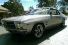
150mm x 38mm aluminium toroid
The whole resonator. I still need to replace the ground line with a heavier cable, and cover up that hideous glue connection between the topload support and coil.
The unfinished 555 interrupter and linear-regulated DC supply.
The 47N60F MOSFET half bridge. The heatsinks are a little smaller than I would have liked, but that's all I had laying around. A fan will be mounted above them to help improve the situation. The DC blocking caps are 800VDC 5uF PP snubbers, there's TVSs and ultrafast diodes across each FET and back-to-back zeners across the gate/source. The gate resistors are 12 Ohm, with ultrafast diodes for fast turn-off.
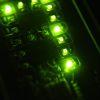
And finally, just for fun, I dug out EVR's old SSTC 1.0 driver and hooked it up to the resonator: The little purple flame is around 2cm long.
Registered Member #33
Joined: Sat Feb 04 2006, 01:31PM
Location: Norway
Posts: 971
Sigurthr wrote ...
I'm all for anyone diving full on in to working out the kinks on the 4046 for SSTC use, as a solid solution would benefit us all. Practical implementation issues aside, the main "failure" modes I've witnessed first hand are the following:
1) PLL won't lock, slams rail to rail trying to lock 2) PLL won't lock, doesn't even try and just sits at the frequency set by trimmer no matter the input signal, or lack there of. 3) PLL locks on to harmonics during ground strike 4) PLL locks initially, then loses lock during ground strike and then can't lock again. It then follows #2. 5) nonlinear tuning range; example: first 40% of resistance value of pot tunes linearly from 450KHz to 580KHz, next 10% of pot the frequency jumps up to 700KHz and VCO increases exponentially with voltage increment from pot up to over 2MHz.
#5 was a circuit someone asked me to debug and not of my own design. #1 was reported by several here on the forum, but I couldn't replicate the issue
I've played a lot with the 4046 (74HC4046) for my induction heater work. There are some traps, and I think I've fallen into every one of them. Along the way, I figured out how to make a stable design, the three crucial points to making a stable design as follows:
1: Phase comparator 2 is nice in that it locks with zero phase offset over the whole frequency range, but it's edge triggered, which is bad news around any noisy power electronics. It can be made to work, but I wouldn't trust it for reliability. Phase comparator 1 with an integrator in the loop will lock with a constant (adjustable, around 90 degrees) phase offset over the whole frequency range. Capture range doesn't make much sense to talk about, since the PLL is essentially trying to lock to itself. The frequency it gets fed with is always the frequency the VCO is running at, only the phase is different.
2: The lock range needs to be limited by limiting the VCO input voltage range. Some 4046es behave strangely around the ends of the VCO input voltage range. Most designs try to choose an appropriate lock range by changing R1/R2/C, but this doesn't help when the VCO does strange things at the ends of the range. This is especially bad with the 74Hc4046, and was the reason for a lot of strangeness in my designs, until I limited the VCO voltage range.
3: The feedback needs to be right. The signal going into pin 14 of the 4046 needs to be strong enough (usually > 100 mV) over the whole frequency range that the VCO can run at, and it needs to be nicely behaved with regards to the phase. Some phase shift difference over the VCO frequency range is acceptable, but if the phase does crazy things then you might get trouble. This ties together with point 2, limiting the lock range makes it easier to design a feedback network that works over the entire range.
Since phase comparator 1 is the best option, you have to live with the 90 degree phase shift. This means that your feedback has to be either tank cap voltage (in a double resonant coil) or tank current shifted by 90 degrees. For a regular SSTC, antenna feedback should work, but I'm not sure how predictable the phase shift is.
If you have trouble with the PLL sticking, not locking or similar, troubleshooting can be done in the following way. Disconnect the output of the loop filter from the VCO input, connect a potentiometer to the VCO input. Disconnect the second phase comparator input (pin 3) from the VCO output and ground it. Use an oscilloscope to observe the output of phase comparator 1 (pin 2) and the VCO output (pin 4). With the resonator connected, adjust the VCO voltage over the range that the loop filter can control it. The phase comparator output and the VCO output should be more or less in phase when above Fres and out of phase below. If the phase shift does strange things or there are glitches, you know the problem. Limit the lock range or improve the feedback network until you get a clean square wave out of the phase comparator. Make sure to run the bridge at a voltage where you won't damage anything when it's out of tune during this procedure.
Registered Member #4074
Joined: Mon Aug 29 2011, 06:58AM
Location: Australia
Posts: 335
Thanks for the info, Sigurthr and Wolfram. Once I've ordered the 4046 ICs this will be very helpful.
I need a sanity check regarding the SSTC's grounding system. I over analyzed it and now I can't decide which option is best. Here's a rough block diagram of the whole system:
The parts I'm fussing over at the moment are the LV DC supply, driver and interrupter, with regard to grounding. Would it be better to: - 1) Connect the common negative LV DC bus directly to the grounded enclosure(s) - 2) Connect the LV DC bus to ground via decoupling caps - 3) Leave the LV DC supply floating (along with the driver and interrupter)
It makes sense to leave it all floating (which appears to be the case in Steve Ward's and Eric Goodchild's Mini and Interrupted SSTCs), but tying the DC rails to mains earth via decoupling caps (just like the 325V DC bus) also seems viable. I'm worried that connecting the negative to earth, or even just adding the decoupling caps, will create a path for interference.
Originally, I planned for the interrupter to be handheld and connected to the coil via a shielded RCA cable, with a 12V wall wart for power. I'm now going to power the interrupter from the same 12V supply powering the driver in the coil. Having two different 12V supplies separated by a few meters and both connected to the coil sounded like a recipe for hard-to-eliminate interference (especially since the 12V wall wart's lead is about 2.5 meters long and will act as an antenna).
Does any of this look correct? If I can get the layout, shielding and grounding correct first, I can hopefully play with different bridges, drivers and feedback methods without trying to debug strange behavior.
This site is powered by e107, which is released under the GNU GPL License. All work on this site, except where otherwise noted, is licensed under a Creative Commons Attribution-ShareAlike 2.5 License. By submitting any information to this site, you agree that anything submitted will be so licensed. Please read our Disclaimer and Policies page for information on your rights and responsibilities regarding this site.


 SSTC feedback and general design