If you need assistance, please send an email to forum at 4hv dot org. To ensure your email is not marked as spam, please include the phrase "4hv help" in the subject line. You can also find assistance via IRC, at irc.shadowworld.net, room #hvcomm.
Support 4hv.org!
Donate:
4hv.org is hosted on a dedicated server. Unfortunately, this server costs and we rely on the help of site members to keep 4hv.org running. Please consider donating. We will place your name on the thanks list and you'll be helping to keep 4hv.org alive and free for everyone. Members whose names appear in red bold have donated recently. Green bold denotes those who have recently donated to keep the server carbon neutral.
Special Thanks To:
Aaron Holmes
Aaron Wheeler
Adam Horden
Alan Scrimgeour
Andre
Andrew Haynes
Anonymous000
asabase
Austin Weil
barney
Barry
Bert Hickman
Bill Kukowski
Blitzorn
Brandon Paradelas
Bruce Bowling
BubeeMike
Byong Park
Cesiumsponge
Chris F.
Chris Hooper
Corey Worthington
Derek Woodroffe
Dalus
Dan Strother
Daniel Davis
Daniel Uhrenholt
datasheetarchive
Dave Billington
Dave Marshall
David F.
Dennis Rogers
drelectrix
Dr. John Gudenas
Dr. Spark
E.TexasTesla
eastvoltresearch
Eirik Taylor
Erik Dyakov
Erlend^SE
Finn Hammer
Firebug24k
GalliumMan
Gary Peterson
George Slade
GhostNull
Gordon Mcknight
Graham Armitage
Grant
GreySoul
Henry H
IamSmooth
In memory of Leo Powning
Jacob Cash
James Howells
James Pawson
Jeff Greenfield
Jeff Thomas
Jesse Frost
Jim Mitchell
jlr134
Joe Mastroianni
John Forcina
John Oberg
John Willcutt
Jon Newcomb
klugesmith
Leslie Wright
Lutz Hoffman
Mads Barnkob
Martin King
Mats Karlsson
Matt Gibson
Matthew Guidry
mbd
Michael D'Angelo
Mikkel
mileswaldron
mister_rf
Neil Foster
Nick de Smith
Nick Soroka
nicklenorp
Nik
Norman Stanley
Patrick Coleman
Paul Brodie
Paul Jordan
Paul Montgomery
Ped
Peter Krogen
Peter Terren
PhilGood
Richard Feldman
Robert Bush
Royce Bailey
Scott Fusare
Scott Newman
smiffy
Stella
Steven Busic
Steve Conner
Steve Jones
Steve Ward
Sulaiman
Thomas Coyle
Thomas A. Wallace
Thomas W
Timo
Torch
Ulf Jonsson
vasil
Vaxian
vladi mazzilli
wastehl
Weston
William Kim
William N.
William Stehl
Wesley Venis
The aforementioned have contributed financially to the continuing triumph of 4hv.org. They are deserving of my most heartfelt thanks.
Hello, i know i should not be doing this (because i still have my DRSSTC pending), but i will try to show a progress of my CNC mill setup. Control electronics will be done with parallel port connected to few Microchips PIC processors (goal is 3 for motor and 1 for LCD Data).
Why so much? Well, when coding i really cannot drive all three motors with one uPC as good as with more of them. Simply if one motor is turning, others has to wait until subroutine ends, this way i can control all at once regardless of state of others.
So, i avoided ttl and logic components, and transformed this schematics into PIC ASM code (sorry for misleading comments, it's in my mother language)
Trick to succesfully use RRF and RLF function is to know where CARRY bit is, and also rotating binary value of "10001000", so at first or last 4 bits, there will be one active bit. It was easy to think, but harder to use in successful program (for me)
This program will be later transformed into 8, maybe 14 pin PIC (2 extra pins for incrementing and decrementing value). Power part will contain L293D 4x half bridge (which was already successfully tested on breadboard).
!! Code removed due to obsolence, if you need updated one, just send me PM !!
Hello, this is not dead yet, i just do not have any time in summer. So, a few updates-
1. succesfull build of stepped driver for bipolar stepper motors (it can use 4,5 or 6 wire steppers) 2. build of "embedded computer" with pic 16LF877A for this thing, to show coordinates and control gantry
Now for a few questions - i will use parallel port with optical isolation, i have some basic schematics in my mind, i also tried it with 2 pins and it did not worked out - i think reason of this is that i used mach 3 in win7 and mach3 advises to use XP or older... ( :( ) For this purpose i have one old pc in my shelf, just get that old OS somewhere...
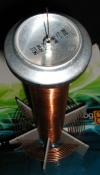
For spindle i plan to use motor from my mini chinese dremel copy, which i hope will work for time i get most of the bugs out of that...
pic 1 - stepper driver with pic16f628a, 4 leds that indicates current step phase and L293D
pic 2 - my "embedd system" which contains 20x4 LCD, pic16f877a, to right you can barely see icsp header for pickit3, one header down for keyboard (6 pin ports - PORTA), other 2 8bit ports are covered by lcd
pic 3 - below is my soldering and pcb design, i think this was too small for me
pic 4 - my pic16f84a testing program - i cannot use this because this doesn't have no of i/o ports i need
But i need some help - i cannot get LCD of my embedded system start to work... cursor of that is blinking, also it is moving, but not a single character can be shown. could someone more skillfull help?
Code removed for space reason, looked ugly
EDIT: i think there is something about port setting, something that 16f84 does not have...
I am searching for some 877 sample codes, for now without luck but i found out some ADCON setting (which i think is analog to digital converter), Edit2 - internal pullup setting does not work (BCF OPTION_REG,7) also output pins are ok, i scoped nice 4ms square wave of every one on port B, so pullups are working, but whole thing is not ok. I also tested LCD and it works ok with old circuit on breadboard. I have it connected through whole port b and port e, which can be seen from code.
First - i hope you all see images above and in this post.
Well, i am still tinkering with my mini lcd thing, so while i wont solve this, i did some mechanical stuff, this was done in 2x 2 hours after work today and yesterday,
This will be X axis, rails are 55cm long, but i will move only half of that length, so around 20cm of working space, and appx. same will be for Y axis. There are already two step/dir motor drivers, which i am going to modify a little (using few outputs of pic16f628a which drives them to control my LCD thingy) I need to have my spindle closest to center of the rails as possible (to use as much of those 55cm), which means i first have to build Y and Z dollies and then center it. Dollies will use simple small bearings against those aluminum profiles. They are not exactly straight, but - oh well, this is just for testing purpose, i'll be happy if i will be at least able to control something with pc. Upper aluminum will not be like on photo, but vertical for easier dolly setup. Or maybe i will use two metal rods from some printer, i currently have my hands on.
For leadscrew, i am using M6 threaded rods, which means for 1 turn i have exactly 1mm move. for current steppers that gives me 1/48=0,021mm - but lets say 0,025mm accuracy per step.
It seems this won't be as boring winter.
-----------------------------------------
--------------------------------------------------
-------------------- Edit 10th december 2013
little cad porn, this is to help me visualize before making y axis... this could work, but most of things i made usually dont, so i hope i wont be dissapointed at the end.
After year, things are getting a lot slower than i thought...
Upper "PIC embedded solution" will be divided into few more separate, but simpler (to program) circuits - 3 axis dimension display with 7segment LED display, and one master unit which will constantly monitor overcurrent for motors, axis limit tactile sensors, and after start will make homing and possibly control gantry with manual override, with (2x16 lcd / LED) indications of errors. My stepper driver will be modified (code + some wires on few tactical spots :) ) to obey limit sensors. (why oh why i did not add some additional input connectors on pcb... )
Here comes what i've done (in last week) -built x axis bed - this looked pretty easy until it showed my x axis rails are bent, oh ... for now, it will do. Missing stepper motor holder (70% done) -built y axis rails, dolly (x2), bearing holders, y axis side aluminum base, missing only holders for y axis rails (8x L shaped profiles). Pre-drilled to accept stepper motors and mate with base that holds x axis. (90% done)
Does not look that much but it was lot of drilling, filing, CADing, marking, measuring and mainly thinking about making use of materials i have limited resource of, so using as maximum possible usage of material with minimum waste is a must. Most parts are from printers, scanner and so. Those rails especially are hard to get, not even two identical ones. Eagle eyed viewer can see i won't have that much use of long x rail due to short dolly - that is right, as now i don't have any other bigger flat material to use.
Below picture of nearly finished y rail with x rail below and x + y dollies. - due to fact i have only table drill and dremel (not able to produce anything in cnc or with any high precision at all), i am quite happy with precision i can get from these tools
More images here (picasaweb)
-nearest things to do 1.finish y rail bed; make holder for x axis stepper motor, make base for z axis (will use 180mm long rails, i am not desided if rails should be steady or moving, will need a lot of CADing and thinking)
This site is powered by e107, which is released under the GNU GPL License. All work on this site, except where otherwise noted, is licensed under a Creative Commons Attribution-ShareAlike 2.5 License. By submitting any information to this site, you agree that anything submitted will be so licensed. Please read our Disclaimer and Policies page for information on your rights and responsibilities regarding this site.


 CNC mini mill