If you need assistance, please send an email to forum at 4hv dot org. To ensure your email is not marked as spam, please include the phrase "4hv help" in the subject line. You can also find assistance via IRC, at irc.shadowworld.net, room #hvcomm.
Support 4hv.org!
Donate:
4hv.org is hosted on a dedicated server. Unfortunately, this server costs and we rely on the help of site members to keep 4hv.org running. Please consider donating. We will place your name on the thanks list and you'll be helping to keep 4hv.org alive and free for everyone. Members whose names appear in red bold have donated recently. Green bold denotes those who have recently donated to keep the server carbon neutral.
Special Thanks To:
Aaron Holmes
Aaron Wheeler
Adam Horden
Alan Scrimgeour
Andre
Andrew Haynes
Anonymous000
asabase
Austin Weil
barney
Barry
Bert Hickman
Bill Kukowski
Blitzorn
Brandon Paradelas
Bruce Bowling
BubeeMike
Byong Park
Cesiumsponge
Chris F.
Chris Hooper
Corey Worthington
Derek Woodroffe
Dalus
Dan Strother
Daniel Davis
Daniel Uhrenholt
datasheetarchive
Dave Billington
Dave Marshall
David F.
Dennis Rogers
drelectrix
Dr. John Gudenas
Dr. Spark
E.TexasTesla
eastvoltresearch
Eirik Taylor
Erik Dyakov
Erlend^SE
Finn Hammer
Firebug24k
GalliumMan
Gary Peterson
George Slade
GhostNull
Gordon Mcknight
Graham Armitage
Grant
GreySoul
Henry H
IamSmooth
In memory of Leo Powning
Jacob Cash
James Howells
James Pawson
Jeff Greenfield
Jeff Thomas
Jesse Frost
Jim Mitchell
jlr134
Joe Mastroianni
John Forcina
John Oberg
John Willcutt
Jon Newcomb
klugesmith
Leslie Wright
Lutz Hoffman
Mads Barnkob
Martin King
Mats Karlsson
Matt Gibson
Matthew Guidry
mbd
Michael D'Angelo
Mikkel
mileswaldron
mister_rf
Neil Foster
Nick de Smith
Nick Soroka
nicklenorp
Nik
Norman Stanley
Patrick Coleman
Paul Brodie
Paul Jordan
Paul Montgomery
Ped
Peter Krogen
Peter Terren
PhilGood
Richard Feldman
Robert Bush
Royce Bailey
Scott Fusare
Scott Newman
smiffy
Stella
Steven Busic
Steve Conner
Steve Jones
Steve Ward
Sulaiman
Thomas Coyle
Thomas A. Wallace
Thomas W
Timo
Torch
Ulf Jonsson
vasil
Vaxian
vladi mazzilli
wastehl
Weston
William Kim
William N.
William Stehl
Wesley Venis
The aforementioned have contributed financially to the continuing triumph of 4hv.org. They are deserving of my most heartfelt thanks.
Registered Member #51
Joined: Thu Feb 09 2006, 04:17AM
Location:
Posts: 263
I have been wanting to build one of these for a while now. I will be attempting to use the bang-bang control method that everyone else has had success with. Here are some pictures of what I have so far. The schematic is for the buck converter. The secondary geometry is a copy of what Eric Goodchild used as far I could tell.
Registered Member #51
Joined: Thu Feb 09 2006, 04:17AM
Location:
Posts: 263
The toroid with the green wire is for the inductor for the buck converter. It is 65 turns of 10 AWG wire on a T300-2D powered iron core. It measures about 95 uH.
Everyone else uses gaped ferrite for this inductor. I was not able to find any cheap and large ferrite cores to wind my inductor on so I went with a toroid. Type 2 material has a low permeability so will not saturate even at a few hundred amps. Because of this the inductor does not require any added air gap.
It is possible that the core will be too lossy but I suspect it may well work. I also considered using an air core but I decided that the leakage would be too high and may cause interference with the control electronics.
Registered Member #2292
Joined: Fri Aug 14 2009, 05:33PM
Location: The Wild West AKA Arizona
Posts: 795
All your power electronics and secondary look great, very clean, and well made BTW! Much better than my first QCW setup.
Are you sure it's not going to saturate at a couple hundred amps? Seems a little pie in the sky for a core of that size.
If you haven't already I would do a saturation test on your inductor. Rig up an SCR, large electrolytic , PSU and current shunt. Fill the cap up to say 30 or 50V with the PSU and discharge it into the inductor with the SCR and watch the resulting current waveform through the inductor with the current shunt on a scope.
For ferrite you will see something like this
The knee in the current is the saturation point in which the inductance starts to roll off.
For powdered iron the role off will be much slower. But generally after it has rolled off enough to stop properly filtering you will start to see problems. Due to the buck drive frequency mixing with the inverter frequency and causing havoc with your primary feedback.
Just out of curiosity what is the value of your filter cap on your buck and what frequency is it going to run at?
Registered Member #162
Joined: Mon Feb 13 2006, 10:25AM
Location: United Kingdom
Posts: 3140
Don't know if it helps but I calculate 2.55 A in that inductor for 100 gauss = 0.01 T (2.55A pk @ 500 kHz to 1 MHz, 10Apk @ 50 kHz to 100 kHz etc.) More likely to melt the insulation than saturate the core I guess.
(from L=N.phi/I, phi = B.Ae, and L=Al.N^2 ... NI = B.Ae/Al)
Registered Member #51
Joined: Thu Feb 09 2006, 04:17AM
Location:
Posts: 263
Eric, I did the test you suggested and found no signs of saturation. I only charged my cap to 36V so I was only able to push about 100A through this inductor before the cap was out of energy.
Simulation confirms that it takes a lot of current to saturate this material.
From the slope of the graph (100A in 368 uS) I calculated the inductor has a value of 128 uH. I also measured the inductance by resonating it with a 100 nF cap and found a value of about 95 uH. The simulation seems to suggest I should have about 100 uH at DC. Who knows which number is really right but any of these values would be reasonable.
I used a 0.01 Ohm shunt resistor and a 1X probe so the scope shows 50A per division. I did not have a big SCR so I used half of an IGBT brick to do the switching.
The only concern I have now is excessive loss in the core material.
I plan on using 25 uF of total filter capacitance on the output of the buck converter. This includes the decoupling capacitor across the full bridge. LT spice simulation shows the max operating frequency of the buck converter is about 30 kHz.
Registered Member #2292
Joined: Fri Aug 14 2009, 05:33PM
Location: The Wild West AKA Arizona
Posts: 795
Well go figure, that's one heck of a core for it's size! Looks like it started to roll off at around 125A more than plenty for that bridge. I guess all you have to worry about is the looseness, but hey it's hobby grade so long as it's not on fire, exploding, melting, smoking, or glowing it's working (for the most part).
You may also find that you can run faster on that semikron, I found rather low switching losses with CM300 and CM600s in my buck even running close to 60KHz and they are way slower than those semikrons.
Registered Member #51
Joined: Thu Feb 09 2006, 04:17AM
Location:
Posts: 263
Eric, looking at the design of the buck converter you have on your website I see you use a FOD3184 to drive each of the IGBTs. Did you ever find that these overheat? I suspect that each gate of my IGBT brick will be about 15nF. This is a fairly large load to drive at say 50kHz. I would like to be able to run my buck converter continuously and have it put out say 150V and not have the IGBT driver section overheat.
I currently have an IXDI604SIA selected to drive each IGBT gate and two IXDI604SIA's in a full bridge to drive the transformer for my isolated gate supply.
I went ahead and had some of the parts of the primary laser cut out of 1/4" white acrylic.
Registered Member #2292
Joined: Fri Aug 14 2009, 05:33PM
Location: The Wild West AKA Arizona
Posts: 795
My gate drivers never overheated, matter in fact they worked rather well all the way up to about 70KHz. I picked those drivers because they had the opto for the high side driver already built in and they are rated to 9A if I remember right. Your bricks are also going to have a much lower gate C than the IGBTs I used in my buck. What I really had trouble with was the the linear V-regs I used to provide the 24V to the gate drive chips. They overheated on occasion and in hindsight it would have been a good idea to go with a custom SMPS to provide the isolated 24V rails.
Registered Member #195
Joined: Fri Feb 17 2006, 08:27PM
Location: Berkeley, ca.
Posts: 1111
I prefer the IXDD614CI because it is a TO-220 package and can easily be heat sunck. Dip packages can't despite the amount of switching cycles it takes for continuous duty. each time the gate chip is between switch cycle the ic is in a linear state and those dips cant store the heat. I use isolated transformer supplies instead of a buck converter type supply and fiber optics instead of optos. f/o's are a little more expensive than opto's but I feel that it is cleaner. I can run these boards to 500khz, usually the IGBT's can't keep up. if you want a circuit it is easy to make.
This site is powered by e107, which is released under the GNU GPL License. All work on this site, except where otherwise noted, is licensed under a Creative Commons Attribution-ShareAlike 2.5 License. By submitting any information to this site, you agree that anything submitted will be so licensed. Please read our Disclaimer and Policies page for information on your rights and responsibilities regarding this site.


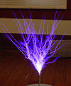
 An attempt at a QCW DRSSTC design