If you need assistance, please send an email to forum at 4hv dot org. To ensure your email is not marked as spam, please include the phrase "4hv help" in the subject line. You can also find assistance via IRC, at irc.shadowworld.net, room #hvcomm.
Support 4hv.org!
Donate:
4hv.org is hosted on a dedicated server. Unfortunately, this server costs and we rely on the help of site members to keep 4hv.org running. Please consider donating. We will place your name on the thanks list and you'll be helping to keep 4hv.org alive and free for everyone. Members whose names appear in red bold have donated recently. Green bold denotes those who have recently donated to keep the server carbon neutral.
Special Thanks To:
Aaron Holmes
Aaron Wheeler
Adam Horden
Alan Scrimgeour
Andre
Andrew Haynes
Anonymous000
asabase
Austin Weil
barney
Barry
Bert Hickman
Bill Kukowski
Blitzorn
Brandon Paradelas
Bruce Bowling
BubeeMike
Byong Park
Cesiumsponge
Chris F.
Chris Hooper
Corey Worthington
Derek Woodroffe
Dalus
Dan Strother
Daniel Davis
Daniel Uhrenholt
datasheetarchive
Dave Billington
Dave Marshall
David F.
Dennis Rogers
drelectrix
Dr. John Gudenas
Dr. Spark
E.TexasTesla
eastvoltresearch
Eirik Taylor
Erik Dyakov
Erlend^SE
Finn Hammer
Firebug24k
GalliumMan
Gary Peterson
George Slade
GhostNull
Gordon Mcknight
Graham Armitage
Grant
GreySoul
Henry H
IamSmooth
In memory of Leo Powning
Jacob Cash
James Howells
James Pawson
Jeff Greenfield
Jeff Thomas
Jesse Frost
Jim Mitchell
jlr134
Joe Mastroianni
John Forcina
John Oberg
John Willcutt
Jon Newcomb
klugesmith
Leslie Wright
Lutz Hoffman
Mads Barnkob
Martin King
Mats Karlsson
Matt Gibson
Matthew Guidry
mbd
Michael D'Angelo
Mikkel
mileswaldron
mister_rf
Neil Foster
Nick de Smith
Nick Soroka
nicklenorp
Nik
Norman Stanley
Patrick Coleman
Paul Brodie
Paul Jordan
Paul Montgomery
Ped
Peter Krogen
Peter Terren
PhilGood
Richard Feldman
Robert Bush
Royce Bailey
Scott Fusare
Scott Newman
smiffy
Stella
Steven Busic
Steve Conner
Steve Jones
Steve Ward
Sulaiman
Thomas Coyle
Thomas A. Wallace
Thomas W
Timo
Torch
Ulf Jonsson
vasil
Vaxian
vladi mazzilli
wastehl
Weston
William Kim
William N.
William Stehl
Wesley Venis
The aforementioned have contributed financially to the continuing triumph of 4hv.org. They are deserving of my most heartfelt thanks.
Registered Member #146
Joined: Sun Feb 12 2006, 04:21AM
Location: Austin Tx
Posts: 1055
Hi Guys,
Recently got a project running here thats been a lot of fun. Well, asfun as fiddling with electronics stuff gets... I think this one certainly pushes the state of the art in terms of tesla coils driven by electronics! I'll cut to the chase with a link to some pictures of the device:
See more here:
Where to begin...
Essentially its a DRSSTC that runs extra long pulses to grow sparks at a low voltage of about 55kV pk. I believe the reason the sparks stay pretty straight instead of splitting is that the low voltage allows growth only with negative coronas, which have been shown to make branchless sparks, whereas positive coronas tend to branch. But this is merely my speculation! I've not seen any research on spark development under these conditions (~400khz).
In order to maximally control the straightness of the sparks, the electronics driving the primary circuit are fairly sophisticated. Essentially im using a "phase shifted full bridge", where 1 leg of the AC output is perfectly in phase with the primary current (so it experiences wonderful zero current switching), but the other leg of the AC output is phase shifted, which essentially controls the drive voltage. If the 2 AC legs are 0 degrees phase, then the effective output voltage (differential mode) is zero. If the 2 AC legs are 180 degrees, then the entire 395V is applied to the primary circuit. So what happens is the phase is "ramped" over a period of about 17mS in order to gradually drive more and more power into the coil. This allows for growing long straight sparks that do not branch. If the voltage (or phase) is ramped too quickly, the sparks become very forked and jagged, forming multiple branches in 1 shot. This parameter is of course tweakable during operation .
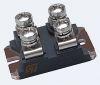
The bridges themselves utilize some cheap little IGBTs (FGH60N60SMD). Each bridge has been tested to 60A peak, hard switched (due to the phase shifted bridge control) for 17mS pulse durations at 400khz. The calculated thermal rise for the die is 52*C during such a pulse. Luckily real operation is not this harsh.
The output of 2 bridges (operating synchronously) is combined through a pair of transformers, with the secondary windings in series. Each transformer is wound 6:3, so with 2 combined, its a 1:1 ratio. The reason for doing this is 1) i can ground one end of the primary now, and 2) it absolutely forces equal current sharing between the 2 H-bridges.
Power is derived from a 22.2V 5000mAHr LiPo battery, the type used for RC helicopters. It only lasts for about 8 minutes of continuous fun as the DC-DC converter uses about 700W. The DC-DC conversion itself is a resonant type converter used very commonly for capacitor charging supplies, as its short-circuit tolerant. The DC bus for the bridges is then 395VDC with 20,000uF of storage capacity. One spark eats up 200-250 Joules of this capacitors energy, so even 20k uF is a bit insufficient, the DC voltage drops by about 30V at the end of the 17mS burst.
Another interesting feature of this system is a secondary MMC. That is, there is a string of 72 x 1.2nF 700VAC capacitors INSIDE of the secondary coil. This capacitor adds about 17pF to the coil. There are a few reasons for this. 1) due to the gigantic streamers this thing produces, detuning is a serious issue, so the coil needs to have a pretty decent amount of self capacitance. 2) more Csec drops the impedance of the coil, which seems to improve spark growth behavior. 3) adding more energy storage to the secondary coil means slightly less circulating current in the primary. The way i think of it is that the system Q probably stays about the same, but since there is more energy in the secondary, there is less stored in the primary. This capacitor also provides convenient measurement of the toroid voltage by measuring the current through this capacitor only. This is where i obtained the 55kV number, which is in good agreement with previous direct HV measurement of my last QCW system using a Jennings HV vacuum cap divider. So indeed, the voltage is low.
The primary coil is wound with home-made Litz wire. 4 bundles of 4 strands of 24awg were twisted such that each strand sees the outside equally. Its important to do this, otherwise strands that remain burried inside the bundle will not carry their share of current. This is more surface area than 1/4" copper tubing at a fraction of the size and weight. Only needed about 18 feet of the litz, so it wasnt a big deal to make it using a drill with a jig.
Grounding for the system is questionable! To be totally un-tethered, i have a pair of shoes with steel mesh on the bottom for contact with the floor (dont stand on anything flammable!). My body is charged to a few kV with the 2.5A of secondary ground current. Generally, though, i prefer to add an additional connection to mains ground. The current into mains ground is about 1.5A, meaning my body capacitance is still seeing about 1A in this condition. I'm uncertain of the effects of this current through my body (it must primarily go through my right arm, which is gripping the conductive gun grip which is the only connection between me and the electronics). Anyone have any research on RF currents in the human body? People expose themselves to pretty similar fields when playing with SSTCs and VTTCs, just being up close to the secondary coil must induce quite a bit of current in them (according to the mutual capacitance between the person and the TC).
Well, im sure i forgot to describe certain aspects of the project, so ask questions if you like.
EDIT: I should have mentioned that my shoes have wires to connect the steel mesh to the electronics ground. My body only carries capacitive (displacement) current due to my physical location near a HVRF voltage source.
Registered Member #2919
Joined: Fri Jun 11 2010, 06:30PM
Location: Cambridge, MA
Posts: 652
WOW! So I guess this is the evolution of the QCW - phase shift control eliminates the huge DC-DC converter that feeds the bridge. Are you doing any kind of regulation, or does the "bus modulation" (which is kind of a stretch since the bus voltage stays constant) just run open-loop? It's amazing that you can get such sparks with only 60A...does your regular QCW do that? How long are the sparks?
Registered Member #162
Joined: Mon Feb 13 2006, 10:25AM
Location: United Kingdom
Posts: 3140
That is truly awesome !
I think we all want one.
"I'm uncertain of the effects of this current through my body (it must primarily go through my right arm, which is gripping the conductive gun grip which is the only connection between me and the electronics). Anyone have any research on RF currents in the human body?"
Purely anecdotal; a colleague at work used to be a technician/engineer servicing amateur radio stuff at a famous specialist retailer, there were many 'silent key' sales ...due to neck, throat, facial etc. cancers of the right side - where hand held antennas were used.
Probably worth running a wire from the gun directly down to earth / the mesh shoes ..... better safe than sorry.
Registered Member #146
Joined: Sun Feb 12 2006, 04:21AM
Location: Austin Tx
Posts: 1055
So I guess this is the evolution of the QCW - phase shift control eliminates the huge DC-DC converter that feeds the bridge.
Correct, you just have to account for the extra turn off loss (the turn on loss is zero, however, as its ZVS naturally). The FGH60N60SMD has very good turn off characteristics, and handles hard switch-off at 60A without problems. I looked at adding a turn off snubber, but it didnt seem necessary, and would restrict how close to 180* phase i could get.
Are you doing any kind of regulation, or does the "bus modulation" (which is kind of a stretch since the bus voltage stays constant) just run open-loop?
I tried to close the loop in my micro controller, but could not stablize it (i needed to add some loop phase but never got time to try this out). It runs open loop for now, which seems to be fine. I even thought to compensate for the power factor of the phase shift bridge, but i dont think its that critical, so the phase is a linear ramp for now.
It's amazing that you can get such sparks with only 60A...does your regular QCW do that? How long are the sparks?
Ive recorded up to 56" sparks with 100Apk in the primary (so 50Apk per bridge). Adding the MMC to the secondary not only improved spark length by about 10" (compared to a higher inductance coil, with only a toroid), but dropped the primary current from ~120A to 100A. I also tested 2 MMC caps inside there for 33pF, it seemed to perform about the same, so i decided to keep it with just 1 MMC and have the other as a spare.
My previous QCW system made longer sparks, but used more current too. My best setup could do 65" sparks with about 140Apk in the primary, using a 16" toroid to keep the coil impedance down, and help steer the sparks.
Registered Member #1134
Joined: Tue Nov 20 2007, 04:39PM
Location: Bonnie Scotland
Posts: 351
As usual, amazing work!
This particular part interests me:
Steve Ward wrote ...
Another interesting feature of this system is a secondary MMC. That is, there is a string of 72 x 1.2nF 700VAC capacitors INSIDE of the secondary coil. This capacitor adds about 17pF to the coil. There are a few reasons for this. 1) due to the gigantic streamers this thing produces, detuning is a serious issue, so the coil needs to have a pretty decent amount of self capacitance. 2) more Csec drops the impedance of the coil, which seems to improve spark growth behavior. 3) adding more energy storage to the secondary coil means slightly less circulating current in the primary. The way i think of it is that the system Q probably stays about the same, but since there is more energy in the secondary, there is less stored in the primary. This capacitor also provides convenient measurement of the toroid voltage by measuring the current through this capacitor only.
Is there any reason why this couldn't be done on an ordinary DRSSTC?
The reason I ask, is that for very small coils, it seems you could easily drop the fres to something a little more manageable, using a string of caps as well as a topload.
Registered Member #146
Joined: Sun Feb 12 2006, 04:21AM
Location: Austin Tx
Posts: 1055
Probably worth running a wire from the gun directly down to earth / the mesh shoes ..... better safe than sorry.
Yes, these wires already exist. There is just the unavoidable issue of mutual capacitance between me and the tesla coil, my body will always be part of the local environment, so i will always have some current going through me.
Your radio technician story is pretty scary. I probably want to limit my exposure as much as possible.
Is there any reason why this couldn't be done on an ordinary DRSSTC?
The reason I ask, is that for very small coils, it seems you could easily drop the fres to something a little more manageable, using a string of caps as well as a topload.
Les
I see no reason why not. You just need a lot more caps in series as the top voltage for a typical DRSSTC is much higher. Keeping the string of caps inside the secondary coil is important so that its got proper field grading around the caps. If you tried to make the MMC external to the secondary, designing it to not break down would be much harder i think. Its probably also a good idea to pot the thing, but ive left mine unpotted for now.
I havent experimented with lowering the impedance of a "typical" DRSSTC secondary, maybe there is some benefit.
Registered Member #146
Joined: Sun Feb 12 2006, 04:21AM
Location: Austin Tx
Posts: 1055
This phase shifting idea is rather clever, care to share any more details on how it was accomplished?
Im sure theres probably an easier way, but mine involved an atmel Xmega16A4 micro controller, a Xillinx XC9536 CPLD, and some ultrafast comparators and a few other little bits.
There is the usual predictor zero cross detector, which feeds into the CPLD.
The CPLD generates a trigger (about 100nS long) every time the zero cross detector transitions. This trigger discharges the capacitor of a PWM ramp generator.
The PWM ramp starts ramping up right after each zero cross detection. The ramp is fed into another ultrafast comparator along with a reference voltage generated by the xmega's DAC (this voltage sets the PWM duty cycle, or phase, essentially). The output of this PWM comparator is fed back into the CPLD.
From here the CPLD has both the zero phase signal from the prediktor, and a PWM'd version of it. Theres a bit of logic to spit these signals out to the gate drivers. Essentially all the IGBT turn on events are synchronized, just that the turn off of one half bridge is variable and early (this is what the PWM stuff was all for). This is very similar but different to a true phase shifted H-bridge, but the operation is exactly the same due to the nature of the load.
Because the load is inductive, turning off early causes the output voltage to commutate (as you forward bias the freewheeling diode) so that the opposing IGBT turns on with zero voltage across it (current transitions from wheeling diode to IGBT upon current reversal). This is often called "class DE" i believe. For this reason, i actually make all the IGBTs turn off at least ~150nS before the actual current zero crossing, so that there is sufficient load current to commutate the output voltage and provide ZVS. This is mainly because these IGBTs are more efficient at turning off than turning on! It also eliminates any forced diode recovery, so the switching waveforms are quite clean, even when hard switching 50A.
The other useful thing i implemented was having the micro-controller start the coil oscillating. The micro spits out 4 to 5 cycles at 400khz to drive the bridge, before giving the command to the CPLD to switch over to the feedback input. This greatly improves the reliability of starting the system at low supply voltages, AND allows some control into biasing what pole/mode the coil operates at (this can be problematic at some tunings).
The Xmega performs over-current limiting and generates the long-term ramp for spark growth.
If people really want to see schematics and code, i suppose i can post it, but its probably only useful if you are really serious about building your own. Its a much higher level of complexity compared to the old "universal driver".
Registered Member #30
Joined: Fri Feb 03 2006, 10:52AM
Location: Glasgow, Scotland
Posts: 6706
That's awesome! I bet the capacitors inside the secondary coil are really to hit the zombies harder.
I'm interested in the transformer combining scheme, because there's no reason (that I can see) to stop at two bridges. What did you use for DC block capacitors on the primary side?
I don't believe the radio ham cancer story. Every old radio ham I've known was also a heavy smoker and chronic breather of solder fumes.
This site is powered by e107, which is released under the GNU GPL License. All work on this site, except where otherwise noted, is licensed under a Creative Commons Attribution-ShareAlike 2.5 License. By submitting any information to this site, you agree that anything submitted will be so licensed. Please read our Disclaimer and Policies page for information on your rights and responsibilities regarding this site.


 ArcAttack! Tesla Gun


 .
.


 I bet the capacitors inside the secondary coil are really to hit the zombies harder.