If you need assistance, please send an email to forum at 4hv dot org. To ensure your email is not marked as spam, please include the phrase "4hv help" in the subject line. You can also find assistance via IRC, at irc.shadowworld.net, room #hvcomm.
Support 4hv.org!
Donate:
4hv.org is hosted on a dedicated server. Unfortunately, this server costs and we rely on the help of site members to keep 4hv.org running. Please consider donating. We will place your name on the thanks list and you'll be helping to keep 4hv.org alive and free for everyone. Members whose names appear in red bold have donated recently. Green bold denotes those who have recently donated to keep the server carbon neutral.
Special Thanks To:
Aaron Holmes
Aaron Wheeler
Adam Horden
Alan Scrimgeour
Andre
Andrew Haynes
Anonymous000
asabase
Austin Weil
barney
Barry
Bert Hickman
Bill Kukowski
Blitzorn
Brandon Paradelas
Bruce Bowling
BubeeMike
Byong Park
Cesiumsponge
Chris F.
Chris Hooper
Corey Worthington
Derek Woodroffe
Dalus
Dan Strother
Daniel Davis
Daniel Uhrenholt
datasheetarchive
Dave Billington
Dave Marshall
David F.
Dennis Rogers
drelectrix
Dr. John Gudenas
Dr. Spark
E.TexasTesla
eastvoltresearch
Eirik Taylor
Erik Dyakov
Erlend^SE
Finn Hammer
Firebug24k
GalliumMan
Gary Peterson
George Slade
GhostNull
Gordon Mcknight
Graham Armitage
Grant
GreySoul
Henry H
IamSmooth
In memory of Leo Powning
Jacob Cash
James Howells
James Pawson
Jeff Greenfield
Jeff Thomas
Jesse Frost
Jim Mitchell
jlr134
Joe Mastroianni
John Forcina
John Oberg
John Willcutt
Jon Newcomb
klugesmith
Leslie Wright
Lutz Hoffman
Mads Barnkob
Martin King
Mats Karlsson
Matt Gibson
Matthew Guidry
mbd
Michael D'Angelo
Mikkel
mileswaldron
mister_rf
Neil Foster
Nick de Smith
Nick Soroka
nicklenorp
Nik
Norman Stanley
Patrick Coleman
Paul Brodie
Paul Jordan
Paul Montgomery
Ped
Peter Krogen
Peter Terren
PhilGood
Richard Feldman
Robert Bush
Royce Bailey
Scott Fusare
Scott Newman
smiffy
Stella
Steven Busic
Steve Conner
Steve Jones
Steve Ward
Sulaiman
Thomas Coyle
Thomas A. Wallace
Thomas W
Timo
Torch
Ulf Jonsson
vasil
Vaxian
vladi mazzilli
wastehl
Weston
William Kim
William N.
William Stehl
Wesley Venis
The aforementioned have contributed financially to the continuing triumph of 4hv.org. They are deserving of my most heartfelt thanks.
Registered Member #1938
Joined: Sun Jan 25 2009, 12:44PM
Location: Romania
Posts: 699
Motivation/Short Intro For my High voltage experiments, knowing the exact potential difference of a given supply value would be extremely useful. So I decided to build a high voltage probe, using a resistive divider. After doing some calculations, I decided to go for a 1:1000 divider ratio, for the many advantages including ease of reading the measured values (10kV -> 10V). The High voltage goes as Vin, and the measurement is done at Vout. I needed a 1GOhm resistor, so I purchased 5x 200MO Vishay Dale High voltage resistors from Ebay. Connecting them in series I get the desired value:
To insulate this resistor, I put it in a PVC pipe under oil:
If R1 is 1GOhm, and R2 is 1MOhm, the voltage drop across R2 , Vout will be aprox. 1/1000 * Vin . Instead of R2 I use a multimeter with 1MOhm impedance (However, to protect the multimeter, additional components are required). The results:
The left picture shows a good result: for 30.3V in, the multimeter measures 32mA, very close to the 1/1000 ratio (actually the ratio is 1/1001).
Use the probe for HV Exactly as Proud Mary suggested, I had to "throw away" the multimeter, and get a good old analog microAmpmeter. -to be continued-
Old issues - fixed - please read the entire thread However, trying to use this probe with my 50KV cascade supply, gives very poor results. The multimeter jumps between values, the biggest shown is 12 (12KV). Probably because of the high frequency currents. Any idea on what am I missing? Do I need a capacitive divider? Do I need a combination of the two? Thanks.
Registered Member #543
Joined: Tue Feb 20 2007, 04:26PM
Location: UK
Posts: 4992
Your '50kV cascade' supply seems to be a Cockcroft & Walton voltage multiplier, which has a DC output.
A voltage divider measurement network is suitable for use in DC and low frequency AC measurements, so this is not your problem.
Saying that your multimeter has an input impedance - Z - of 1M, is not at all the same as thinking of the meter as a simple 1M resistance - R - across the terminals. This is your problem, Radhu.
What will be a big problem is if your meter goes open circuit - when 50kV will appear at the bottom end of your 1G resistor.
Here is what you must do: throw away the meter with 1M input impedance and buy another with the standard Zin = 10M.
Connect a resistor of 1M1 from the bottom of the 1G resistor and the Earth. (Connect a neon or zener across this resistor for safety) Measure the voltage across this with your 10M input impedance meter and all will be well.
Registered Member #1938
Joined: Sun Jan 25 2009, 12:44PM
Location: Romania
Posts: 699
Thanks for your reply and suggestions! I'll try to do the mods tomorrow and hope for better results.
Initially I planned to use two resistors R1-1GO and R2-1MO as per the schematics above. However I quickly learned that the multimeter's impedance will change the results. That's why I excluded R2 and simply used the multiplier with it's internal 1MO impedance. I would really need some clarification on why it works like this, when testing with a small voltage supply even if I'm mixing things (Rs with Zs)
I do have a better multimeter with 10MO impedance, and other features, but I don't want to put that anywhere close to the 50KV supply. I also have a digital 1MO impedance multimeter that I was planning to embed into this probe. Why do you think it is a must to use a 10MO multimeter?
About the Zener and the Neon: indeed a most welcomed protection, I already tried paralleling a Neon over the Multimeter's terminals but it was changing the measurements. I've seen this while testing the "probe" with small voltages. Probably my mistake, will try that again (since a neon glass lamp should be somewhere close to 200GO?)
"Avram Iancu - pehblendã / oxid de uraniu nativ" Thanks for mentioning Avram Iancu over "Dracula" . Much appreciated.
Registered Member #543
Joined: Tue Feb 20 2007, 04:26PM
Location: UK
Posts: 4992
radhoo wrote ...
Thanks for your reply and suggestions! I'll try to do the mods tomorrow and hope for better results.
Initially I planned to use two resistors R1-1GO and R2-1MO as per the schematics above. However I quickly learned that the multimeter's impedance will change the results. That's why I excluded R2 and simply used the multiplier with it's internal 1MO impedance. I would really need some clarification on why it works like this, when testing with a small voltage supply even if I'm mixing things (Rs with Zs)
I do have a better multimeter with 10MO impedance, and other features, but I don't want to put that anywhere close to the 50KV supply. I also have a digital 1MO impedance multimeter that I was planning to embed into this probe. Why do you think it is a must to use a 10MO multimeter?
About the Zener and the Neon: indeed a most welcomed protection, I already tried paralleling a Neon over the Multimeter's terminals but it was changing the measurements. I've seen this while testing the "probe" with small voltages. Probably my mistake, will try that again (since a neon glass lamp should be somewhere close to 200GO?)
"Avram Iancu - pehblendã / oxid de uraniu nativ" Thanks for mentioning Avram Iancu over "Dracula" . Much appreciated.
Think of your two resistors in series: 1000M and 1M - a simple ratio of 1000:1.
Now, if I take a second resistor of 1M, and connect that in parallel with the first resistor of 1M, we have a resistance of 1/R = 1/R1 + 1/R2 which is 0.5M - 500K.
So we have a ratio of 1000M/0.5 = 2000:1 by using your 1M meter, which will be completely incorrect!
Now, if you take a 10M resistor (think of your meter), and connect that in parallel with your 1M, we have a combined resistance of 910K - so here your voltage divider would have a ratio of 1000:0.95 - no good to us!
But if we make the bottom resistor in the potential divider 1.111Meg-ohms (or 1M111 as we write it) we find that when we put this in parallel with your 10M resistor we have exactly 1M - and the 1000:1 ratio has been preserved! For all ordinary purposes, you can use a resistor of 1M1 as the bottom resistor, which we call the measuring resistor in this circuit.
Registered Member #1938
Joined: Sun Jan 25 2009, 12:44PM
Location: Romania
Posts: 699
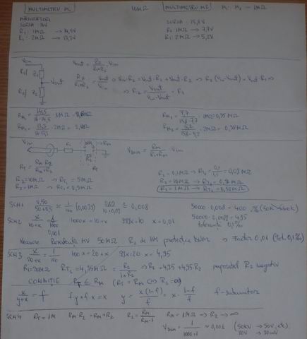
yes, thanks for the examples, I did most of these scenarios on a piece of paper, however I still don't understand why the divider works without using R2, relying only on the multimeter's impedance (which is 1M):
Taking this another example:
The author speaks about R3, the internal resistance of the DMM. Before picking my multimeter I did some measurements like: Known voltage supply, measured by the multimeter in series with a 1MO resistor (, where resulted that my multimeter can work in a divider as a factor of 1MO.
Moving further, since I still have the question of impedance vs. resistance (unfortunately I did a different school), I see the following on Wiki: Electrical impedance, or simply impedance, describes a measure of opposition to alternating current (AC). Electrical impedance extends the concept of resistance to AC circuits, describing not only the relative amplitudes of the voltage and current, but also the relative phases. When the circuit is driven with direct current (DC) there is no distinction between impedance and resistance; the latter can be thought of as impedance with zero phase angle.
All my tests have been performed in DC (except measuring the 50KV supply that may still show some ripple), so the 1MO impedance multimeter performed as a 1MO resistor. So this is the answer to my question.
On repairfaq, the author further says: While R2 is not strictly needed, it is recommended that it be included and approximately equal to the Z-in of the meter on the scale you will be using. The reason to include R2 is to insure that high voltage never can reach the meter. I've seen this article before building my probe and probably this was another reason I dropped the resistor relying only on the multimeter's resistance.
However now I'm back to the start. Why doesn't this work?
Registered Member #543
Joined: Tue Feb 20 2007, 04:26PM
Location: UK
Posts: 4992
Here is what to do.
Buy an old Russian moving coil 50μA panel meter and use this in series with your 1G resistor. You will have 50μA= 50kV. End of story.
For safety's sake, you should connect a small neon bulb and a zener in parallel with the meter, so that if the meter fails and becomes open circuit - a very rare event, but possible - then the neon and zener will conduct away high voltage appearing at the end of the 1G resistor. If the zener should also fail, the neon will start to conduct.
Registered Member #1938
Joined: Sun Jan 25 2009, 12:44PM
Location: Romania
Posts: 699
Thanks Proud Mary, for bearing with me on this one and for the practical advise, I'll look around for an old uA meter, but while I do that, I'm still intrigued about the poor results in my first attempt, using the DVM.
I need to understand the failure reasons. Did you (or others on the forum) perhaps tried to build a probe and maybe have a clue on this?
Registered Member #543
Joined: Tue Feb 20 2007, 04:26PM
Location: UK
Posts: 4992
radhoo wrote ...
Thanks Proud Mary, for bearing with me on this one and for the practical advise, I'll look around for an old uA meter, but while I do that, I'm still intrigued about the poor results in my first attempt, using the DVM.
I need to understand the failure reasons. Did you (or others on the forum) perhaps tried to build a probe and maybe have a clue on this?
I think it's because the DMM input has some active devices in it - it's not just a resistance going straight to Earth - and perhaps the DC is 'dirty' with switching waveforms imposed upon it. I'd guess that if you used your C&W 'cascade' to charge a capacitor - say a Leyden Jar - and then measured the voltage across that, it would work properly. But do be careful if you try this, or you will be toast, my friend!
Registered Member #1938
Joined: Sun Jan 25 2009, 12:44PM
Location: Romania
Posts: 699
it's hot glue.
The first end (with the pipe empty of oil) was simply sealed with a perfectly matching cylinder of glue bar, and the resistor's connector inserted though it. Additional hot glue was added to ensure sealing.
The other end could not take a sealing bar since the air inside would have been compressed. So I carefully sealed it with hot glue, directly over the oil's surface. Not even one bubble of air left.
This site is powered by e107, which is released under the GNU GPL License. All work on this site, except where otherwise noted, is licensed under a Creative Commons Attribution-ShareAlike 2.5 License. By submitting any information to this site, you agree that anything submitted will be so licensed. Please read our Disclaimer and Policies page for information on your rights and responsibilities regarding this site.


 DIY High voltage probe


 "Link2")

